OXIDIZER SERVICE SERIES: PART 1
Part of properly servicing your oxidizer system is maintaining the design documentation associated with that system. When it comes to oxidizer design, National Fire Protection Association (NFPA) standards are considered good practice.
The following are critical design documents oxidizer users should save that contain information required by the NFPA to implement an overall system reliability plan. Anguil uses the same documents to offer value-added service, regardless of the original manufacturer.
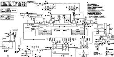
- Process and Instrumentation Diagram (P&ID): The P&ID is the command drawing that summarizes instrumentation, safety devices, operational limits, and control loops. The P&ID typically provides the oxidizer component tag numbers, as well as the number, and type, of process exhaust pick-ups for the system. The system utility requirements and performance parameters may be listed as well.
- Electrical Schematics: Electrical schematics provide detailed connectivity of the system and are an important tool used for troubleshooting. It is critical the electrical schematics are not only readily available but also revised to stay current with system changes.
- Sequence of Operation / List of Set Points & Alarm Conditions: The sequence of operation is a step-by-step description of how the oxidizer is designed to operate. This includes how the unit starts, how the process exhaust is brought on-line, how airflow and temperature control are maintained, and how the unit safely shuts down. Set points and alarm conditions of the system are also included in this document. It is important to note that this documentation is required per the National Fire Protection Association’s NFPA 86: “Wiring diagrams and sequence of operations for all safety controls shall be provided” (From NFPA 86: Standard for Ovens and Furnaces, 2019 Edition – Section 4.1.1.2).
- Programmable Logic Controller (PLC) Program: If your system requires a PLC, we recommend keeping a fully documented copy of the PLC program for your records. Some oxidizer suppliers may be reluctant to release this information to system end-users because PLC programs can include proprietary control schemes. However, with a signed confidentiality agreement in place, end users should be able to obtain this code. If your oxidizer manufacturer is no longer in business, it is possible to upload the program directly from the PLC. If this is the case, the program may be undocumented, and you may need an oxidizer service provider to re-enter the code documentation. Information on Anguil’s PLC programming capabilities can be found here.
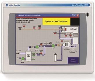
- Human Machine Interface (HMI) Program: The HMI (Operator Interface / Operator Touch Screen) is the operator’s window into the workings of the oxidizer’s PLC. The HMI program connects with the PLC program to control your oxidizer system by displaying data points from the PLC along with set points and tuning parameters. An operator can adjust the set points and tuning parameters from the HMI. The HMI provides system status or alarm messages based on the PLCs outputs. In the event the display fails, you should be prepared to download your HMI program to a replacement display from your spare parts inventory.
- Expected Pressure-Temperature Profile: It is critical to know your pressure point values to set up a regular inspection plan for your maintenance personnel. Ideally, you should have a table showing expected pressure and temperature data at the common process exhaust airflow amounts your production requires. If this is unknown, ask your system provider to provide data for two conditions: at full-oxidizer airflow capacity and at half-oxidizer airflow capacity. Using this data, you can approximate the points between when establishing your customized inspection checklists.
- Permit Compliance Documents: Compliance documentation requirements vary across local, state, and federal agencies, making it difficult to provide a generalized recommendation. Anguil recommends organizing your permit compliance documentation in a single document that includes minimum temperatures, operating temperatures, and bypass limitations. This document will keep all parties aware of the key compliance parameters to monitor and record with respect to your oxidizer system.
- Bill of Materials / Recommended Spare Parts Lists: A complete bill of materials will allow you to know the replaceable parts needed to maintain system operation. Ideally, the parts listed in the Bill of Materials would be further categorized as “Critical Spare Parts,” “Recommended Spare Parts,” “Consumable Spare Parts,” “Convenience Items,” “Long Lead Time Components,” etc. This enables operators to decide on the type and quantity of spare parts to stock based on specific production and compliance requirements. Some air permits require critical spare parts to be kept on hand. More detailed information on these categories can be found on the Spare Parts section of our website.
Here are some additional highlights regarding system documentation from the current edition of NFPA 86 Standard for Ovens and Furnaces 2019 Edition:
- 4.1.1.1 Plans shall be drawn that show all essential details with regard to location, construction, ventilation, piping, and electrical safety equipment. A list of all combustion, control, and safety equipment giving manufacturer and type number shall be included.
- 4.1.1.2 Wiring diagrams and sequence of operations for all safety controls shall be included.
- 7.3.3 Operating instructions that include all of the following shall be provided:
- (1) Schematic piping / wiring diagrams
- (2) Startup procedures
- (3) Shutdown procedures
- (4) Emergency procedures
- (5) Maintenance procedures
- 7.3.4 When the original equipment manufacturer no longer exists, the user shall develop inspection, testing, and maintenance procedures.
This is the first of four parts in Anguil’s Oxidizer Service Series. We encourage you to also view Part 2: Crafting Your Oxidizer Maintenance Plan as well as Part 3: Stocking Spare Parts for Your Oxidizer System and Part 4: Oxidizer System Optimization.