 The Challenge
The United States EPA promulgated a ruling in 40 CFR, imposing strict new standards to reduce emissions of toxic air pollutants from the manufacture of pharmaceutical products, including prescription and over-the-counter drugs. The agency’s rule was intended to reduce emissions of a number of air toxins and hazardous air pollutants (HAPs), including methylene chloride, methanol, toluene and HCI. It was estimated at the time that the ruling would reduce air toxins annually by approximately 24,000 tons or 65 percent from contemporaneous levels. The affected pharmaceutical manufacturing processes included chemical synthesis (drawing a drug’s active ingredient) and chemical formulation (producing a drug in its final form).
The Solution
One of the approximately 100 facilities affected by the ruling was a pharmaceutical plant in upstate New York. Determined to stay below acceptable MACT levels, the company set out to establish compliance needs and subsequent direction by contracting with a consultant to formulate a compliance plan. The result was a specification package that required oxidation and caustic scrubber technologies.
 The Result
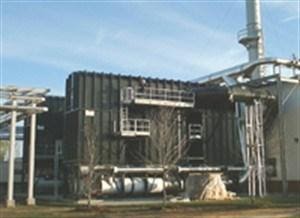
Specifically, the design included a primary and backup system, each consisting of two 35,000 SCFM (56,175 Nm3/hr) regenerative thermal oxidizers (RTOs) and two 35,000 SCFM (56,175 Nm3/hr) caustic scrubber systems. The RTOs were to process the emissions, including methylene chloride, acetone, ethanol, isopropyl, alcohol, methanol and mineral spirits, and were designed to achieve over 99-percent destruction efficiency. The scrubbers were designed to process treated gases and achieve 99.5-percent reduction of the HCI derived from the oxidation process. After the design phase, the two technologies were selected in order to oxidize the VOC/HAP compounds, and to remove the resultant HCI emissions from the outlet of the oxidizer. Upon receipt of the specification package, the engineering staff at Anguil began to design the system within the boundaries of the specifications.
The specification package included the following requirements and parameters:
Process producing emissions – multiple (~60) sources including:
- Conservation vents
- Reactor vents
RTO materials of construction:
- Refractory selection: The RTO included the installation of high-purity ceramic fiber insulation, because of its resistance to HCI attack.
- Purification chamber outer skin: The purification chamber was constructed of 0.25 inch A36 Steel. It was internally blasted and coated with a vinyl ester corrosion-resistant coating. This coating resists any HCI (vapors or condensed acid) that could potentially reach the RTO shell behind the insulation. The coatings were pigmented so that the first coating was light gray and the second coat was dark gray. This allowed a visual inspection to identify that the coating was thoroughly applied during fabrication, and provides an easy means of checking for coating degradation after operation.
- Ceramic media support grid: The ceramic media support grid was constructed from Hastelloy C276 in order to support the ceramic media. This “cold face” has the potential too see condensed acid gas. Hastelloy C276 provides high strength and resists both chloride stress corrosion cracking and chloride pitting and crevice corrosion.
- Inlet plenum: The inlet plenum is the duct located underneath the RTO that connects to the three inlet butterfly diverter valves. The air flowing through this duct to the RTO contains VOCs and HAPs but does not contain acid gases. However, as a precaution against corrosion, this ductwork was constructed of AL-6XN, a corrosion resistant alloy.
- Outlet plenum: The outlet plenum is the duct located underneath the RTO that connects to the three outlet butterfly diverter valves. The air flowing through this duct to the RTO contains acid gases. This ductwork was constructed of Hastelloy C276.
- Bed/plenum/hopper: The plenum beneath each of the three ceramic media support grids was constructed of Hastelloy C276.
- Butterfly valves (bed inlet, outlet and purge): The three inlet diverter valves process air containing VOCs and HAPs. The three outlet diverter valves contain air containing acid gas. All sic valves were constructed of Hastelloy C276. The three purge valves were also constructed of Hastelloy C276.
- Transition to acid gas scrubber quench: The transition from the RTO outlet plenum to the acid gas scrubber quench contains acid gases. This ductwork was also constructed of Hastelloy C276.
Floor sweeps:
- Waste stream flow rate: 6,500-35,000 SCFM (10,432.5-56,175 Nm3/hr)
- Waste stream temperature: 50 to 100ºF
- VOC/HAP breakdown
The company possessed a long history treating halogenated compounds, including oxidation and acid gas scrubbing equipment. The two RTO and scrubber systems supplied here were actually installed after a smaller oxidizer and scrubber was operational within the same facility.
General Operational Description
Designing the oxidizer first, engineers specified that each RTO would process up to 35,000 SCFM (56,175 Nm3/hr) of VOC/HAP-laden air, providing 99.5% destruction efficiency.
Pharmaceutical Industry Pollution Control Solutions
The oxidizer consisted of three reinforced, insulated, steel chambers filled with high-temperature, structured ceramic energy recovery media. Each oxidizer would utilize two burners to maintain its oxidation temperature set-point, and provide even temperature distribution within the combustion chamber for maximum VOC/HAP destruction. Located below each of the energy recovery chambers would be inlet and outlet diverter valves and the associated air duct plenum passages. These would allow the process airflow to be diverted into and out of each of the heat recovery chambers. One duct would act as an inlet to the energy recovery chamber, the other as an outlet from the chambers to the acid gas scrubber. A third, smaller duct would direct heated purge air to each chamber. A purge valve for each chamber would control the flow of purge air into the chamber. The directional mode and purging would be controlled by a PLC program, which would change the direction of airflow at regular intervals to optimize system efficiency. The typical flow directions within the RTO would be adjusted every 90 seconds.
In operation, solvent-laden air (SLA) would enter the oxidizer via an energy recovery chamber, where the high-temperature ceramic heat transfer media would rapidly preheat it prior to its introduction into the oxidation chamber. After the chemical oxidation purification reaction occurs, the hot, clean, outgoing gas would heat the exit energy recovery chamber.
The SLA flow direction would be switched at regular intervals to maintain optimum heat recovery efficiency by the automatic diverter valves on demand from the PLC control system. After serving as an inlet, an energy recovery chamber would be purged for a cycle before serving as an outlet. This ensured that all air that entered a bed would be treated to the maximum extent possible. With sufficient concentration of hydrocarbons would self-sustain the oxidation process. The oxidizer can be operated in an off-line bake-out mode to allow the removal of organic buildup on the heat exchange media. The potential organic material consists of methylcellulose and lactose. In the bake-out mode, the RTO/scrubber trains are taken offline from the process. At a reduced airflow, the outlet temperature is allowed to rise before the flow direction is switched. This hot air vaporizes organic particulate collected on the cold face of the heat exchange media. The flow direction is switched and other cold faces are cleaned in succession.
Process Air Flow
Two 35,000 SCFM (56,175 Nm3/hr) systems were specified to provide redundancy while processing flows from 6,500 SCFM (10,432.5 Nm3/hr) to 35,000 SCFM (56,175 Nm3/hr). Each RTO/scrubber train would be functionally equivalent and operate in conjunction with or independent of each other. Each system could be returned down 6:1 (5,850 SCFM, 9,389.25 Nm3/hr). If the airflow to an individual RTO/scrubber was reduced below this level, a pressure control loop could open the fresh air damper to maintain the minimum system airflow. Butterfly isolation dampers were included at the inlet and outlet of each RTO/scrubber. The inlet isolation damper would be used to isolate an RTO/scrubber train during startup and shutdown. The outlet isolation damper would be activated when the RTO/scrubber was not in use. Butterfly isolation valves were included downstream of the scrubber; the manually operated valves would be used to isolate the RTO/scrubber train for service. A flanged blind was also included for installation downstream of the scrubber for isolation during service.
Fan Location
The RTO processes corrosive HCI vapors as the chlorinated hydrocarbons are oxidized. In a forced draft arrangement, the RTO is under positive pressure. In that configuration, the corrosive gases will tend to leak to atmosphere at the instrumentation (thermocouple) penetrations and the corrosive gases will condense at this interface corroding the outer shell. Therefore, an induced draft arrangement is typically preferred for chlorinated RTO applications. A fan was designed for the conditions at the scrubber outlet, including a radial blade fan wheel constructed of a corrosion resistant alloy, Hastelloy C276, and a carbon steel housing lined with rubber. This type of fan wheel was not as efficient as backward inclined or air foil designs, but it would not be as sensitive to aerosol droplets and offered a lower tip speed, reducing fan noise.
99.5% Destruction Efficiency Design
A residence time of two seconds at 1650°F was proposed to achieve an average destruction efficiency of 99.5 percent. Actual compliance test data demonstrated destruction efficiency in excess of 99.9 percent. In order to guarantee the high destruction efficiency that this project required, additional steps were taken to reduce the air not fully treated when the airflow changed direction. For the 99.5-percent destruction guarantee, the system was designed with three chambers. At any one time, one chamber would act as an inlet and one as an outlet, while the third was being purged. After serving as an inlet chamber, each chamber would be purged with heated clean air during the next cycle. The purge air would be heated to minimize the potential for HCI gas water vapor condensation and the resultant corrosion potential, even though high nickel and molybdenum alloys were used to resist corrosive effects. It would then become an outlet chamber during the next cycle. The three-chamber design also minimized any inlet/outlet bypass during valve cycling.
Acid Gas Scrubber
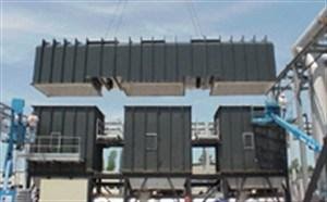
The acid gas scrubber was designed to process the maximum exhaust capacity of the RTO exhaust, including the purge air containing HCI vapor, providing 99.5-percent HCI removal. The horizontal quench was designed to cool the RTO exhaust to approximately 150°F. The re-circulation pumps provided water into the adiabatic quench through three separate spray headers. The air temperature was reduced to 150°F at the quench outlet. The water that was not evaporated flowed to the recycle sump. Approximately 50 percent of the HCI was scrubbed in the scrubber quench. The air left the horizontal quench and entered the bottom of a counter-current packed tower scrubber. Water and caustic solution was sprayed on the top of the tower. The remaining acid gases were absorbed by the solution as the air passed up the column. The air passed through a mist eliminator to remove entrained water before exiting the scrubber column. A sodium hydroxide solution was added to the re-circulating water to neutralize the adsorbed HCI and form sodium chloride (salt water), the sodium hydroxide addition rate controlled by pH analyzer. Salt water blow-down was controlled by a conductivity analyzer and by adding makeup water, causing sump overflow. The company worked closely with the customer and the consultant throughout the bid process, suggesting options and clarifying details on this major environmental project, and was also commissioned to install the systems. A tight site location necessitated the careful use of over-sized cranes so as to ensure no interference with or rupture of critical plant gas, air and nitrogen lines. Heavy rains throughout much of the process further complicated installation but ultimately the installation of all the equipment and the tie-in of the ductwork, electric and controls, without affecting process, were achieved. The result was a system, which surpassed the customer’s objective of 99.5 percent destruction efficiency and ensured compliance with the EPA’s pharmaceutical MACT.

 The Challenge
 The Result