


Multi-Staged Combustion or Selective Catalytic Reduction?
Comments Off on Multi-Staged Combustion or Selective Catalytic Reduction?The Challenge
Many industrial furnaces operate in oxygen depleted conditions, emitting high levels of ammonia, NOx, and other nitrogen-bearing compounds. This presents a significant challenge for manufacturers striving to meet air quality regulations and limit carbon output.
Emission streams that contain nitrogen bearing hazardous air pollutants (HAPs) cannot be thermally treated in a traditional oxidizer system without forming additional NOx, making adherence to an air permit difficult or impossible. In such cases, a secondary abatement device, downstream of the thermal oxidizer is required for additional NOx reduction.
Historically, the industry has relied on Selective Catalytic Reduction (SCR) systems to achieve this. The add-on technology injects ammonia or urea into the process stream before passing it through a specialized catalyst that converts the NOx into nitrogen gas (N2) and water vapor. However, this approach comes with significant operational burdens:
- The need for ammonia or urea storage, pumps, and customized control systems to maintain injection rates.
- High operating costs due to chemical consumption, catalyst maintenance, and periodic replacement.
- Fresh air must be added to dilute the inert process streams to safe levels, increasing the treatment volume and leading to condensation issues.
- Additional winterization equipment to prevent freezing in cold water climates.
It essentially requires a small chemical operation to remove the NOx and the staff to support it.
The Solution
Over the past four decades, Anguil has provided thousands of thermal and catalytic oxidizers around the world, many of which incorporated SCR technology. Recognizing the inefficiencies, engineers at Anguil came up with a better solution. The objective was to maintain very high levels of HAP removal, eliminate the catalyst and associated maintenance, prevent the need to dilute the stream making it safer to operate, and eliminate the use of add-in chemicals.
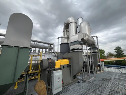
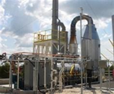
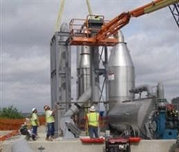
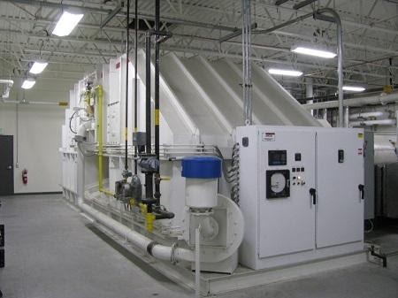
This solution was a Multi-Staged Direct Fired Thermal Oxidizer (MS-DFTO) – a groundbreaking approach that compartmentalizes the oxidation process across multiple temperature-controlled stages with varying oxygen levels, to dramatically reduce the formation of greenhouse gases.
In the MS-DFTO the nitrogen bearing HAPs are introduced into the first stage of the thermal oxidizer, the reducing zone, that operates at elevated temperatures, but without oxygen. This serves to disassociate the HAPs while not forming NOx from any nitrogen bearing compounds in the absence of oxygen. Special operational sequences ensure starved oxygen is maintained in the first stage. The high temperature, oxygen depleted gas leaving this first stage is then rapidly cooled in a second stage to near the oxidation temperature. At this cooler temperature, the gases are reintroduced to air in the third chamber where the complete combustion of compounds occurs. Design considerations are made to ensure that the temperature after oxidation does not escalate to where thermal NOx could be formed, generally above 1,800°F (982°C).
Specialized refractory insulation and highly automated controls for the various stages of the Anguil MS-DFTO minimize auxiliary natural gas consumption. Properly staging the operating conditions and temperature profile throughout the MS-DFTO will result in destruction rates of the hazardous compounds and volatile organic compounds with minimal NOx formation in a single system.
In select applications, a fourth stage of the MS-DFTO has been added to provide Selective Non-Catalytic Reduction (SNCR) as a safety factor to ensure even fewer NOx emissions. Experience has shown that these fourth SNCR stages are not necessary and rarely used even when supplied as the NOx emissions have always met permit requirements without the need for this polisher.
The Result
This staged combustor from Anguil is reshaping how industries approach greenhouse gas abatement from process furnaces. On this application, the Anguil MS-DFTO was treating 5,000 SCFM (8,025 Nm3/hr) of process air in a single abatement device with well over 99% HAP destruction and NOX emissions that were a small fraction of the allowable permit value. The equipment does not require chemical injections or active catalyst maintenance, meaning a heavily reduced operational cost relative to an SCR. Inert process streams can remain inert, meaning a safer system can be supplied that does not require upstream dilution. Treating a fraction of the air also means the upstream process ducting can be smaller, saving cost all around.
Industrial facilities continue implementing Environmental, Social, and Governance (ESG) strategies to comply with regulations, improve sustainability, and meet stakeholder expectations. This ESG initiative met those objectives and reduced equipment cost, footprint, and maintenance costs, while eliminating the carbon footprint from past chemical purchases.
Onsite Wastewater Treatment for an On Point Budget
Comments Off on Onsite Wastewater Treatment for an On Point BudgetThe Challenge
A global manufacturer of key chemical ingredients used in a wide array of products including clothing, carpeting, automobile thermoplastics, computer cases, and sporting equipment, was planning a facility relocation and expansion that presented a significant wastewater treatment challenge.
At their previous location, the manufacturer was using a perozone system to treat their cyanide-laden wastewater. However, the system as designed could not meet the rigorous discharge standards of the local Publicly Operated Treatment Works (POTW) on the order of 0.04 ppm. Further, they had abandoned the peroxide injection system to reduce the health and safety risks per a companywide mandate.
The expansion required a relocation to a new facility, but the increased production would also triple the company’s wastewater volume. If they did not find an onsite treatment solution, the hauling and disposal costs were going to dramatically increase operating expenses.
The Solution
Nailing Down the Requirements
Anguil collaborated with the client to understand their specific challenges and determine the project objectives. We gathered benchmark data at the existing facility to identify possible solutions that offer the best return on investment (ROI). Project engineers then worked with the customer to understand their decision-making criteria to evaluate only business viable treatment approaches.
In this case, the client’s priority was to eliminate hauling and disposal costs of their cyanide-laden wastewater. With the expansion at a new facility, they expected their wastewater volume to triple, as well as the corresponding disposal costs. Secondly, they wanted a fully automated system with minimal operator intervention so they could focus on producing products. Third, they wanted to minimize the storage and handling of any noxious chemicals.
Next, water samples were sent to the Anguil lab to validate the different technology considerations. Anguil typically identifies several potential treatment and process options which align with the client objectives, and after presenting these to the customer, collaboratively selects one or several to validate. Anguil proposed several oxidation schemes. The client preferred to move away from ozone and peroxide so alkaline chlorination was selected for this project. It is a well-known method with wide application to similar waste streams and is easily automated.
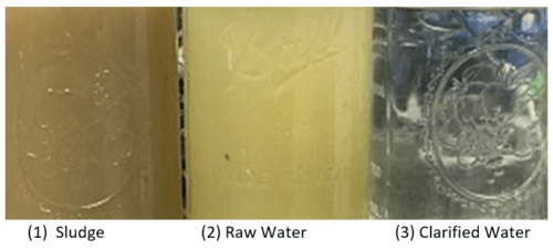
To validate the treatment process, the customer elected for both a bench trial as well as a scaled pilot. For the bench work, the client provided 5 gallons of wastewater collected from their existing facility. Using the required caustic and bleach treatment protocol and measuring free HCN content via the USEPA Pyridine Barbituric Acid Method (Method 10265), test samples were returned which were below the POTW limit of 0.04 ppm. Based on the bench tests results, chemical dosing requirements and costs were easily established before the system was even installed.
Bench Verification
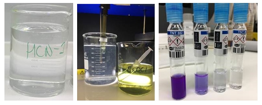
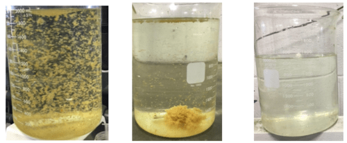
Figure 1 – As received waters from the two (2) drums of HCN wastewater marked 1 and 2 respectively. (Right) HCN wastewater post treatment.
Figure 2 – Example HCN measurements. Non-detect is shown on the right, over range on the left.
After the validation that the method would work, albeit on small sample volumes, the customer requested that Anguil perform a larger pilot study to both validate that larger batch treatments would perform similarly. For the pilot work, the client sent Anguil two (2) fifty-five-gallon drums of wastewater. Adapting an existing pilot system, the same reactions were performed at the previously determined set-points on 15- and 25-gallon batches. Again, final concentrations of HCN were below the required discharge limit. In addition to the further treatment efficacy validation, the chemical dosing requirements were used to estimate yearly operational expenses for the full-scale treatment system as well as size and design the required chemical reagent storage capacity.
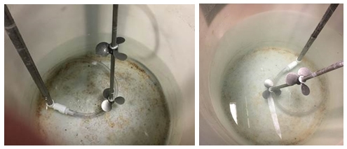
Figure 3 – Appx 15 gallons of HCN wastewater before treatment (left) and after treatment (right). Again, the cloudiness is due to the formation of the precipitate.
Putting it all Together
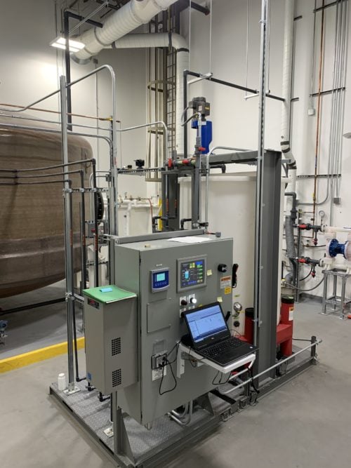
The final step in the process is the system design, realization, and installation. Anguil put together the proposal for a fully automated batch treatment system to handle their expected treatment volumes. The proposal contained specifics on many mechanical components including the tank, pumps and mixer sized as well as the advanced automation and controls – including integration with their existing infrastructure and DCS system – to meet their requirements. Additionally, the appropriate service options for installation, installation supervision, commissioning, and training were included. After the system was installed, Anguil performed a 3-day start-up and training including verification of the system’s ability to treat the wastewater. Anguil’s Aftermarket team will be there to service and support the client as needed.
The Result
Anguil’s approach to solving a client’s wastewater problem is to take a wholistic view of the challenge with a series of go/no go steps throughout the process. Project Engineers are always focused on the customer’s business objectives in a collaborative effort to define an efficient and cost-effective trial to validate treatment approaches that align with their objectives. Through the bench and pilot testing, we offer insight gained along with a comparison of pros/cons of the treatment approaches until we get to the treatment system that aligns with the client needs.
As a system integrator with 35+ engineers and 60+ supporting personnel, we take a technology agnostic approach to help our clients get the system they want. In this case, the results from our effort:
- Client walked through a collaborate process to ensure key decision criteria and objectives were met in a timely and cost-effective manner.
- Customer was able to evaluate various oxidation treatment options that aligned with safety and cost parameters.
- Lab and pilot validation trials confirmed treatment approach and provided operational expense estimates to client as requested.
- Anguil provided a single-source system integration approach that included all engineering (Mechanical, Electrical, CAD, Project Engineering) and support services in-house to mitigate exposure to risk and deliver a fully integrated system with install, commissioning, and training support.
- The treatment approach saved the client considerable amount of money versus hauling and disposal services; providing an ROI estimated in the 14-16 month range.
- Anguil’s electrical engineering team developed the automation and controls to automate the batch-treatment process. This results in minimal human interaction and an extremely efficient process. It also proactively notifies them via text and email of system condition, need for chemical reorder, reporting and remote login capabilities.
Note: At the time of bench and pilot testing this wastewater, Anguil was engaged with a second wastewater produced by the client. We followed a similar approach and validated treatment efficacy through lab and pilot studies. The result of onsite treatment for both wastewaters offered the client an incredible cost savings with minimal impact to resources.
Industrial Wastewater Treatment
Comments Off on Industrial Wastewater TreatmentThe Challenge
Anguil Environmental Systems was asked to supply an oxidizer and packed tower air stripper to treat a 65 gallon per minute water stream containing significant concentrations of Diesel Range Organics (DRO), Volatile Organic Compounds (VOCs) and Total Suspended Solids (TSS). The customer was sending the wastewater stream through a cooling tower which was continually fouling from the DRO present in the water. Significant maintenance costs and production downtime were incurred every time the tower was being brought out of service for cleaning. In addition, the customer was trying to achieve zero VOC emissions from their facility.
The Solution
Application engineers at Anguil determined that a Regenerative Thermal Oxidizer (RTO) would meet the customer’s needs but were skeptical that the air stripper would function properly given the customer supplied water characteristics. Anguil was engaged to evaluate the water stream for the air stripping application. Review of the supplied water analysis indicated that concentrations of the heavier Diesel Range Organics (naphthalene and higher) were beyond their solubility limits. Hence, the presence of free product in this water stream would quickly cause any air stripper to foul, detrimentally impacting stripping performance and potentially creating a safety hazard. Anguil recommended that the customer evaluate oil/water separation and emulsion breaking to remove and potentially recover the free product prior to entering the air stripper.
The Result
Using water samples obtained from the customer, an initial bench evaluation of oil/water separation was conducted. Upon receiving the samples, Anguil realized that either the customer-supplied water analysis was incorrect or that the water samples received were not representative of the customer’s process water since the presence of free product was not observed. The emulsion breaking tests were performed anyway, predictably meeting with little success. In addition to the emulsion breaking tests, Anguil attempted to coagulate the water to determine if this approach would be suitable, determining this method had merit.
Based on results from the initial separation study, Anguil recommended two courses of action. First, the customer would redo their analytical water analysis using suggested test methods to improve confidence in the treatment design requirements. Based on the results of the second round of analytical tests, Anguil suggested that a two stage pilot study be conducted. For Stage 1, Anguil representatives would perform treatability studies on site via jar testing. Based on the results obtained from Stage 1, Anguil engineers would perform a full scale, onsite pilot with the appropriate equipment for Stage 2.
Stage 1: Anguil representatives traveled to the site and performed jar tests directly with the process water in question. Since the process water was at a temperature of 110-120 oF, it was advantageous to work with the process directly rather than trying to ship samples off site possibly compromising their integrity from cooling, biological action or chemical reactions from long hold times. After a number of trials, they successfully determined that the water could be coagulated by raising the pH from 4 to 8.5, utilizing a poly aluminum chloride (PAC) based coagulant blend and a standard polymer. After coagulation and filtration, color, turbidity and solids content were reduced. Anguil then sent the untreated and treated water for third part lab analysis to determine the overall effectiveness of the process. The results were promising and the customer elected to move forward with Stage 2 of the pilot study.
Stage 2: Based on the site constraints and treatment goals, Anguil modified its pilot clarification system to perform the second stage of the study. Equipment arrived onsite,was unloaded and placed within the facility. A generator was rented since the facility could not easily supply the required power. Anguil then proceeded to unpack and plumb the pilot system into the existing process piping.
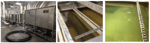
Once everything was set-up, pumps primed and running, the operator filled the tank with process water and began processing using the chemical formula determined in Stage 1: Raise pH > 8.5 using 50% caustic solution, add 300 ppm coagulant, add 1 ppm polymer. As expected, the clarifier influent demonstrated a good floc which quickly began to settle to the bottom of the clarification tank. With continued processing, clarity improvements in the clarification tank became noticeable as submerged parts of the tank became visible as the initial dirty water was displaced by the coagulated and clarified water. Water samples pulled from the clarifier effluent were obviously cleaner than the raw process water, and with continued processing acceptable clarity was achieved.
After successfully demonstrating the clarification process, treated samples were pulled and tested using the same test protocol used in Stage 1. In addition, a sludge sample was sent for benzene analysis in order to determine if the sludge would be considered hazardous. Sludge production rates were quantified by coagulating, flocculating and filtering specific volumes of process water. Filtered samples were wrung dry and air dried for several days. Wet and dried samples were weighed.
The qualitative and quantitative results met the customer’s expectations and treatment goals. The chemical coagulation protocol and clarifier in this pilot work were able achieve a DRO reduction of 85% or greater and an 80% reduction in TSS. Since Anguil was proposing a ballasted floc system for the final treatment system to handle the design flow rate of 65 GPM, another set of samples was taken for ballasted floc testing which achieved similar DRO removal rates but improved on the TSS reduction to less than 1 NTU. After reviewing the sludge production rates and potential hazardous classification for the sludge, the customer asked Anguil to recommend a sludge dewatering system. Further, after reviewing the treatment system capabilities and facility requirements, Anguil recommended removing the air stripper and oxidizer from the scope of supply as it was determined that removing the heaviest organics would solve the facilities heat exchanger fouling problems, and the limited VOC loading did not justify the use of an oxidizer.
Anguil was able to guide the customer through the equipment design and selection process by identifying and rectifying shortcomings in the analytical data, avoiding time and cost specifying and designing equipment which would not address the customer’s project goals. Ultimately, the main benefit of Anguil was determining a solution which did meet the customer’s objectives despite the fact that the selected solution differed greatly from the original request. Onsite jar and pilot tests allowed the customer to become educated and familiar with the treatment process while understanding the benefits, capabilities and trade-offs of the proposed system. Further, being on site allowed Anguil to really understand the customer’s needs and process, allowing them to identify customer process variables which could potentially affect treatment system performance and provide seamless integration of the new treatment system into the existing process.
Superfund Site, Water Pump & Treat
Comments Off on Superfund Site, Water Pump & TreatThe Challenge
Anguil was contracted as part of a team of companies to implement a groundwater pump and treat system intended to remove trichloroethylene (TCE) from a local aquifer designated as a Superfund Site by the Environmental Protection Agency (EPA). Though the site is nestled between the buildings and roadways of  an operating industrial facility, the overall extent of the pump and treat system is expansive. Extraction wells are located over 1,000 ft. from the treatment building, with an additional 1,200 ft. of pipe run to the injection wells. All of the water treatment equipment and main control system were designed to be contained within the new treatment building, while control panels located at the extraction and injection areas were to provide local control and monitoring of the appropriate wells. Everything was to work seamlessly together.
The 500 gallon per minute (GPM) pump and treat system, as well as the overall site plan, were designed by a large engineering, procurement and construction (EPC) firm working on behalf of the responsible party. A general contractor and dedicated installation sub-contractor were selected to prepare the site, drill the extraction and injection wells, install the underground conveyance piping, erect the prefabricated treatment building, install the treatment equipment and perform all the interconnecting piping.
The Solution
Anguil was contracted for two phases of this project. During the design and approval portion, Anguil’s Electrical Engineering and Controls team was asked to review the electrical design and system controls. In addition, Anguil EEs also provided and reviewed the system controls specifications to facilitate approvals from the EPA and Army Corps of Engineers. For the construction phase, Anguil provided and managed the delivery of all the water treatment and water logistics equipment, including the control system and control panels. Furthermore, during the construction phase, Anguil field service engineers provided installation and shakedown assistance for the entire system.
Anguil’s scope of supply included all valves, process instruments and transmitters, water treatment equipment, the exhaust stack, storage tanks, pumps, chemical injection system, motor control system, main building control panel as well as two remotely located panels at the extraction and injection well sites. Further, to the largest extent possible, Anguil was directed to supply the equipment skid mounted, pre-plumbed and prewired.
The Result
Anguil was able to bring additional value to this project by successfully managing the multiple vendors of both the water treatment and controls equipment for the EPC. In particular, Anguil identified low-cost, expedited options to meet the aggressive construction schedule mandated by the EPA penalty deadlines, in some cases cutting long lead times in half. Having a custom solutions integrator on this project was especially valuable when major, unforeseen factory delays occurred. By effectively communicating with the construction team, schedules and resources were adequately adjusted. Further, Anguil was able to manage discrepancies between the selected vendor’s products and customer specifications, achieving the design specifications without sacrificing performance.
Throughout the project, Anguil provided onsite engineering assistance suggesting inexpensive changes, such as relocation of instrumentation or alternate piping plans to the equipment, which improved operations and maintenance activities. From an engineering standpoint, they were able to recommend improvements to customer specifications based on operational experience. These improvements included recommendations to upgrade materials of construction, alterations to process instrumentation, upgrading the size of the control panel touch screen to effectively display control parameters, and addition of important safety features. Furthermore, elimination of the redundant multiple control panels was accomplished by integration of logic into the Anguil supplied main system control panel. Lastly, because of site considerations, Anguil suggested substitution of the originally specified radio communications between the main control panel and remote injection well control panel with fiber optic connectivity. This ultimately resulted in a reduction of Anguil’s scope of supply, but greatly improved the system robustness and reliability.
As the project progressed, Anguil worked with the EPC engineering team on several customer-driven change orders. Most significantly, they worked with the EPC to specify and source additional flow meters for the injection well piping that were capable of accurate operation within the space constraints (limited straight run) dictated by the prefabricated concrete well vaults. Anguil managed ripple effect design changes including upgrading the effluent pump capacity, the motor control center and additional input/output cards for the local control panel – these changes were accomplished with no effect on the overall equipment delivery schedule.
In preparation of system start-up and shake down, Anguil on site personnel verified that all equipment was installed per manufacturer recommendations and was operating correctly. In several instances, they were able to identify equipment which had been installed improperly, delivered incorrectly or specified imprecisely. In most cases, these discrepancies were rectified quickly at no cost to the customer. As Anguil personnel accommodated continuing construction activities, PLC program operation was verified and altered as necessary to provide adequate system control. The final result was a turnkey system that met customer requirements for their commissioning schedule and operational characteristics so the project could start on time and on budget.
PEMACO Superfund Site Remediation
Comments Off on PEMACO Superfund Site Remediation The Challenge
 The Challenge
Pemaco was formerly a chemical facility located in a light industrial and residential area of Maywood, CA, adjacent to the Los Angeles River. No one knows how long hazardous substances had been leaking into the ground but the operations date back to the 1940’s. Up until closure of the facility in 1991, chlorinated solvents, aromatic solvents, and flammable liquids had all been used in the chemical mixing, blending, storage and distribution processes at this location.
After a fire at the abandoned Pemaco location, the Environmental Protection Agency (EPA) was called in to stabilize the site and conduct an emergency assessment to determine the extent of contamination into the soil and groundwater.
The EPA worked with several environmental consultants to define a detailed remediation plan for the superfund site. It was determined that solvents and other compounds from tanks and drums caused soil contamination deeper than 90 feet. A 14-acre groundwater plume that migrated into a complex aquifer system under residential properties threatened local water supply wells with Perchloroethylene (PCE), Trichloroethylene (TCE), Trichloroethane (TCA), Dichloroethane (DCA) and Vinyl Chloride (VC).
The Solution
The remediation technologies used would include Electrical Resistance Heating (ERH), Soil Vapor Extraction (SVE), thermal oxidation, acid gas scrubbing and carbon absorption. The goal was to completely remediate the 1.4-acre site of these Volatile Organic Compounds (VOCs) and redevelop it as a public park. The vapor treatment portion of the project combined ceramic core flameless thermal oxidation (FTO) with acid gas scrubbing, vapor conditioning, and a carbon adsorption polishing step to control potential dioxin emissions.
 The Result
 The Result
Working with several environmental engineering firms and the US Army Corp of Engineers, Global Technologies supplied a 1,000 SCFM (1,605 Nm3/hr) Flameless Direct Fired Thermal Oxidizer (DFTO) with a caustic scrubber for emission treatment from the SVE units. The vapor treatment system was designed to handle typical averages of 315 parts per million (ppm) but capable of maximum spikes up to 25,000 ppm.
The oxidizer was designed to achieve 99.9% destruction of hydrocarbons with a unique gas-fired burner that generates virtually no nitrogen compounds (NOX) during combustion. The patented surface combustion technology ensures that all emissions are exposed to the high temperature zone only along the innermost surface. Another important advantage of this arrangement is that hot combustion gases are completely contained within the burner and the oxidizer outer shell remains cool. Therefore the flameless oxidizer can be processing toxins in a matter of seconds after ignition.
A gas flow control valve was integrated to reduce operating costs. By reducing gas flow as the energy content of the VOCs increases the oxidizer uses less supplemental fuel for combustion. It operates in response to control signals from a thermocouple located immediately downstream of the oxidizer burner.
Downstream of the oxidizer, exhaust gases flow into the integral scrubber quench chamber via Fiberglass Reinforced Polymer (FRP) ducting. Adjacent to the oxidizer, the skid mounted scrubber uses polypropylene packing to treat the acid gases. It was optimized to reduce the water usage without sacrificing spray coverage and the design allowed for a max HCl loading of 472 lbs/hr.
The flameless DFTO and scrubber were arranged in an induced draft configuration, pulling exhaust through the system and keeping it under negative pressure to prevent the escape of any corrosive gases.
The United States EPA filmed a documentary about the Pemaco remedial action for internal training purposes. The documentary highlights several “firsts” for the EPA including the use of a flameless thermal oxidizer for vapor treatment. More information can be found on the EPA website.
Reactor Vent Emission Control
Comments Off on Reactor Vent Emission Control The Challenge
 The Challenge
Many chemical and petroleum companies use batch reactors to make their products. These reactors typically have vents which are opened and closed during emptying, filling, mixing, heating or cooling and other steps of the production process. The gases coming from these vents must be controlled under most government regulations. Often the emissions produced are inert (little or no oxygen) streams with relatively low flow and high concentration of Volatile Organic Compounds (VOCs). In this case, the company was operating several reactors that required venting for depressurizing, filling and mixing. The process flow rate was less than 50 SCFM (80.25 Nm3/hr) and was essentially all light hydrocarbons such as methane, ethane and propane, with some halogenated hydrocarbons.
There are two oxidation strategies for this type of process stream, the first is to dilute the process vent with fresh air. This strategy provides oxygen for combustion and reduces the Lower Explosive Limit (LEL) below 50%, using a conventional oxidizer system. The National Fire Protection Association (NFPA) and FM Global guidelines suggest facilities keep vent collection systems airstreams below the 50% LEL for safety reasons. Because of the high BTU (British Thermal Unit) content of the process vent in this application, it would have required a high volume of fresh air to achieve the necessary LEL condition which would have dramatically increased operating expenses and raised safety concerns.
 The Solution
 The Solution
While the above scheme is sometimes acceptable, Anguil implemented a different, safer strategy for this application. Instead of diluting the process vent with fresh air, designers kept the process stream inert, sending it directly through a burner port of a Direct Fired Thermal Oxidizer (DFTO). Essentially this allowed the combustion device to use the high BTU content as fuel for oxidation.
Once the DFTO is brought up to operating temperature with natural gas, the inert process gases are directed to the burner. During normal system operation, the VOC-laden process vent will fuel the pollution control device. During periods of low process flow or low energy content, supplemental fuel is added to the burner, natural gas in this case, to maintain operating temperature of 1400-1600°F (760°C-870°C) in the oxidizer combustion chamber. A minimum of one second residence time at these temperatures ensures a destruction efficiency of 99%+. An oxygen meter in the exhaust stack ensures that sufficient oxygen was present for complete destruction of the VOCs.
A soft refractory lining inside the oxidizer lets the operator start and stop the system without risk of refractory failure that can occur with other designs. This also allows them to shut down the oxidizer during substantial periods of process downtime without negatively affecting the longevity of the equipment.
For inert gases that contain no halogens or sulfur compounds the hot, purified, gas will be released to atmosphere from the combustion chamber or possibly sent to a heat exchanger for energy recovery. This particular application contained halogenated compounds, therefore the hot exhaust gases leaving the DFTO are directed into a hastelloy quench where they are cooled down before entering a packed bed scrubber.
The recirculation with a caustic solution inside the scrubber removes HCl (Hydrochloric Acid) and HBr (Hydrobromic acid). The scrubbed gases are then pulled into an Induced Draft fan and finally out an exhaust stack. An induced draft fan is used with halogenated streams so that there is no potential for corrosive gases escaping to atmosphere. Any leakage of acid gases will result in substantial risk to equipment longevity and to personnel. These scrubbing systems provide 99%+ removal of the acid gases prior to discharge to the atmosphere.
With these acid gases there is also a potential for corrosion of the oxidizer shell behind the insulation if the metal temperature is below the acid dew point. To prevent that from occurring, the oxidizer is designed with an external shroud to keep the carbon steel shell at a temperature above the acid gas dew point, avoiding corrosion concerns.
The Result
The Anguil System has a complete control system with communication capability to DCS (Distributed Control Systems) systems and modems for remote monitoring / diagnostics. These controls provide for automatic purge, system heat-up and a wide range of operating conditions. Magnetic driven scrubber recirculation pumps and scrubber controls are also provided for automatic operation without personnel adjustments.
Purified Terephthalic Acid Plant
Comments Off on Purified Terephthalic Acid Plant The Challenge
 The Challenge
A major chemical manufacturer required a pollution control system to destroy the halogenated Volatile Organic Compounds (VOCs) emitted during the formulation of Purified Terephthalic Acid (PTA). During the production process, methyl bromide is converted to hydrogen bromide. The pollution control system had to be designed to withstand the corrosive nature of the hydrogen bromide as well as the varying organic loading, which alter the temperature of the abatement system.
The Solution
After a thorough supplier evaluation, the plant selected and contracted Anguil Environmental Systems to solve their VOC emission problem. Because of the high loading of CO and the presence of methyl bromide, Anguil recommended a Catalytic Recuperative Oxidation System. It would utilize a specialized metallic catalyst specifically designed for PTA plant exhausts. Anguil’s success with catalytic oxidation of halogenated compounds and experience integrating control devices into existing processes were crucial factors in the plant’s decision.
 The Result
 The Result
An Anguil catalytic oxidation system designed for 90,000 SCFM (144,450 Nm3/hr) was used to process the airflow. The presence of methyl bromide in the emission stream presented additional design considerations. The catalyst oxidizes the methyl bromide to hydrogen bromide (HBr). If hydrogen bromide drops below its dew point it becomes corrosive to the equipment. The equipment downstream of the catalyst must be engineered to avoid any “cool spots” where the hydrogen bromide can condense.
The heat exchanger is one potential “cool spot.” Without proper design, the heat exchanger could lower the temperature of the air exiting the catalytic oxidizer to below the dew point of hydrogen bromide. To avoid the potential condensation of hydrogen bromide and subsequent corrosion to the system, Anguil incorporated a steam pre-heater on the incoming process stream before the catalytic oxidizer. The exhaust from the PTA plant is heated with a 316L stainless steel plate and frame steam pre-heater. The preheated process air then enters the tube side of the shell and tube heat exchanger. The increased temperature of the process air entering the tube side of the heat exchanger prevents the condensation of HBr on the shell side of the heat exchanger, a critical issue in the overall design of the system.
The process exhaust from the PTA plant varies in organic loading; therefore, the catalytic oxidizer design must accommodate these varying levels with minimal use of auxiliary fuel. This is accomplished by utilizing a bypass on the 316L stainless steel shell and tube heat exchanger. Under low organic loading conditions, the heat exchanger bypass is closed so that the full effectiveness of the heat exchanger is available to preheat the incoming stream. At high organic loading, the outlet temperature of the catalyst is raised, resulting in a high preheat temperature from the heat exchanger. This high preheat temperature could cause overheating and shutdown of the system. The “hot side” heat exchanger bypass supplied by Anguil controls the preheat temperature from the heat exchanger, preventing any high-temperature conditions.
The selection of the proper catalyst that would oxidize both the carbon monoxide and the methyl bromide at low temperatures was critical to the project. Historically, halogenated compounds, which include chlorine, bromine, iodine and fluorine, have had damaging effects on both noble metal and base metal oxidation catalysts. Several significant advances in catalyst technology have occurred in recent years, resulting in the development of catalysts suitable for the air stream under consideration. A platinum/palladium-based catalyst deposited on a ceramic substrate was utilized in this design. Anguil’s proprietary catalyst rack design, including specialty gaskets, eliminated the risk of gas bypassing the catalyst which would result in incomplete destruction.
This Anguil Catalytic Recuperative Oxidation System is currently operating and achieving the regulatory compliance demanded of the PTA plant. With the success of this system, the customer purchased an identical 90,000 SCFM (144,450 Nm3/hr) unit and additional systems were installed for PTA manufacturers in the Middle East and Southeastern United States.
Kiln Emission Control Technologies
Comments Off on Kiln Emission Control Technologies The Challenge
 The Challenge
A specialty ceramic material manufacturer in the United States operates several custom-built furnaces in their manufacturing process. Sometimes referred to as kilns, these high-temperature process devices are generally a major source of air pollutants and require an abatement technology to meet environmental regulations with the state or federal agencies. As is the case with many industrial manufacturing operations, emissions are best destroyed through the use of oxidation technologies. Thermal and catalytic oxidizers utilize temperature, time and turbulence to destroy emissions. This particular manufacturer was operating direct-fired thermal oxidizers, as well as Regenerative Thermal Oxidizers (RTOs) for abatement of the various emission streams at this one facility.
The Solution
For one of these processes, this manufacturer needed an RTO to be installed onto a mezzanine inside the building. A special design was required to fit within the height restrictions, yet tall enough for the RTO to operate. Anguil Environmental designed and built the RTO with high-cell density ceramic media to still get 95% thermal energy recovery, but with a much shorter bed elevation. This, along with other design changes, allowed the equipment to be installed inside the building on the mezzanine with a very short vertical dimension.
Having successfully worked with the company before, they again turned to Anguil for a destruction device for another process within their facility. The preferred location for the installation was equally challenging as the last, also on a mezzanine. In this application, the process exhaust was already quite warm, within the temperature range normally associated with catalytic oxidation temperatures (600°F or higher). Rather than design a heavy RTO to fit into this area, Anguil designed and built a catalytic oxidizer to remove the Volatile Organic Compounds (VOCs) and Hazardous Air Pollutants (HAPs) from their exhaust. Since the process exhaust temperature was already hot enough to sustain high levels of oxidation with the catalyst, the oxidizer was supplied without a heater or a heat exchanger. This allowed for a very simple method of controlling the emissions from the process with reduced capital and installation costs.
On the discharge of a third process line, they were operating an older (non-Anguil) RTO to treat the VOCs and HAPs. This specific process required the use of nitrogen to keep the internal kiln chamber starved of oxygen. The inert gas stream allows their end products to cure properly.
Nearing the end of its life cycle, the aging RTO utilized poppet valves to direct airflow within the destruction device and maximize energy recovery within the oxidizer. This process continues to alternate and repeat during normal operation of the RTO, approximately every three to five minutes. The RTO diverter valves were designed without a pressure relief system, meaning that pulses of pressure were traveling back up the ductwork into the process equipment each time the RTO poppets switched. Internal pressure within the kilns affected the control and usage of nitrogen and negatively impacted the process operation and operating costs.
The RTO technology is generally considered to be the most efficient oxidation device and is therefore the most commonly used. However, this manufacturer was successfully utilizing catalytic oxidizers for emission control on another process and felt one should be applied here as well. They wanted a technology that would not only keep them in compliance, but do it without the pressure pulses that had been negatively impacting the process equipment.
Having supplied both thermal and catalytic oxidizers to this facility before, Anguil was called in once again to evaluate the situation and make equipment recommendations. Anguil, along with engineers at this customer, selected a catalytic oxidizer for this unique process. The Products of Combustion (POC) from any oxidizer are Carbon Dioxide (CO2), water vapor and heat. Anguil designed and manufactured this catalytic system with multiple heat exchangers to utilize the heat generated during combustion. The added benefit of this third Anguil control system is that it re-circulates inert oxidizer POC back into their process.
A secondary heat exchanger downstream of the oxidizer cools the treated air so that it can supply the process with tempered supply gas. To enable reentry into the kiln, oxygen concentrations leaving the catalytic oxidizer are maintained at very low levels with custom designed electronic control systems, supply fans and ductwork. Maintaining low oxygen levels and recirculating this offgas reduces the amount of nitrogen required by the process and therefore lowers operating costs for this production line. In addition, a primary heat exchanger within the oxidizer was designed to minimize fuel consumption of the abatement device itself, using heat from the exothermic reaction to preheat incoming pollutants.
The Result
The 20,000 SCFM (32,100 Nm3/hr), Anguil thermal oxidizer was installed indoors, near the process equipment. To keep it under negative pressure at all times, Anguil manufactured the oxidizer in an induced draft fan configuration. Pulling gases through the system with the main fan ensures that no oxygen depleted gases are emitted into the building where personnel were present.
Anguil differentiates itself from the competition by offering all of the different oxidizer technologies used for the destruction of pollutants. This ensures an unbiased equipment selection for each application based on the destruction requirements, efficiency needs and process parameters. They not only design, manufacture, service and install Regenerative Thermal Oxidizers (RTOs), but also direct-fired, catalytic and thermal recuperative systems. Each one of these oxidizer types uses high temperature combustion in a unique manner to best suit each application.
Formaldehyde Production
Comments Off on Formaldehyde Production The Challenge
 The Challenge
A major chemical manufacturer required a pollution control system with minimal operational cost to destroy the Hazardous Air Pollutant (HAP) by-products of a formaldehyde production process. A key issue was system reliability; the plant operates 24 hours a day and only shuts down once per year for plant-wide preventive maintenance.
The Solution
After thorough technical evaluation, the company selected Anguil Environmental Systems, Inc. to solve their HAPs emission problem and put them in compliance. Anguil installed a catalytic oxidation system that meets all applicable regulatory requirements. The system uses a 65% effective shell and tube heat exchanger that allows self-sufficient operation under normal process loadings.
In the formaldehyde production process, methanol reacts with air in the presence of catalyst to produce formaldehyde. Process yields are normally quite high, with over 95% to 98% of methanol ending up as formaldehyde. Some ancillary compounds are generated in the oxidation process due to catalyst inefficiencies. The emission by-products that require control are carbon monoxide, dimethyl ether, methanol and formaldehyde. Both formaldehyde and methanol are classified as Hazardous Air Pollutants (HAPs) and require stringent emission reduction.
Anguil’s extensive experience with formaldehyde manufacturers helped the company in examining possible pollution control solutions. On this application conditions were favorable to use a catalyst for VOC control. Since the customer uses catalyst in their process, they were comfortable using catalyst for VOC and CO oxidation. In addition, there is a relatively high CO and VOC concentration exhausted from the process which would allow the catalytic oxidizer to function without any auxiliary energy requirement.
A precious metal catalyst was selected as the core of the catalytic system due to its ability to provide 99+% DRE of the formaldehyde, methanol, dimethyl ether, and carbon monoxide at a catalyst bed inlet temperature as low as 525° F (275° C). The catalyst is deposited on a monolithic, honeycomb, stainless steel substrate. The catalyst design minimizes the pressure drop through the oxidizer.
Another cost-effective design feature was the integral 65% effective shell and tube heat exchanger that was selected to preheat the incoming process stream prior to the catalyst bed. The exhaust air from the catalyst outlet is hot sufficient to keep the oxidizer operating at temperature with no auxiliary energy requirements.
Oxidizer warm-up following a plant shut-down was also a crucial design consideration. Neither natural gas nor propane is readily available at many of the company’s formaldehyde plants. For this reason an electric heating system was selected to bring the oxidizer up to the 525° F operational temperature prior to the processing of the plant off-gases. A small pre-heat fan and an electric heater were designed to bring the system up to initial operating conditions. Once at setpoint temperature, the oxidizer process inlet valve is incrementally opened to allow the process exhaust gases. As sufficient CO/HAP/VOC loading enters the oxidizer releasing heat from the exothermic reaction, the electric preheat elements shut off completely. No additional energy is added to the system. In fact, the oxidizer doesn’t even use fan energy since it takes advantage of the process pressure to push through the oxidizer.
The Result
The system is operating and providing well over the 99+% destruction efficiency required. The success of this system resulted in this chemical company purchasing another 25 and counting additional Anguil systems for formaldehyde plants around the world. Anguil’s experience, innovative design and quality manufacturing resulted in another satisfied Anguil customer and a long-term partner with air pollution control.
Cumene Plant
Comments Off on Cumene PlantThe Challenge
An East coast chemical plant that manufactures phenol, acetone and alphametyl styrene from cumene planned to install an air pollution control system to control the Volatile Organic Compounds (VOCs) emitted during their chemical production process. Phenol is consumed internally as an intermediate chemical while the acetone and alphametyl styrene are sold off. Once the chemicals are produced, they are shipped to another plant to make carpet fibers. This plant already had a carbon recovery system in place, but needed a system to control the low concentration residual process stream from the carbon recovery system.
 The Solution
 The Solution
After thorough vendor evaluation, the plant selected and contracted Anguil Environmental Systems to solve their emission problem. The combination of VOCs in the stream and their low concentration made catalytic oxidation the ideal technical choice. Plant engineers had concerns that an oxidation system might have an adverse effect on the precise pressure and volume control required in their production process. Anguil’s experience and success with chemical process applications provided the plant personnel with the confidence that catalytic oxidation was a viable solution.
The Result
An Anguil Model 400 forced draft catalytic oxidizer, rated for 65,000 SCFM (102,512 Nm3/Hr) was selected to process the flow from twenty-five sources of production emissions. As always, Anguil’s engineering staff worked closely with the customer throughout the design and manufacturing processes to ensure that the system precisely met their requirements. The system was sized to provide 99% destruction removal efficiency and 70% thermal energy recovery. The reactor section contains a catalyst bed to oxidize the incoming airflow. The catalyst converts VOCs into carbon dioxide, water vapor and thermal energy.
In order to address the concern of the precise pressure and volume control required for the customer’s production process, Anguil manufactured a four-module, fully welded shell and tube heat exchanger. By using a greater plate thickness, as well as fabricating “ribs” and “dimples” on the plates, a pressure differential of 87.5 w.c. was sustained.
The plant’s process operates 24 hours a day, seven days a week. The oxidation unit is required to run continuously, with 100% up-time to accommodate the aggressive chemical production process.
The Programmable Logic Control (PLC) system was integrated into the customer’s control system and redundancy was designed into the most critical items. A difficult pollution control issue was solved by Anguil, resulting in another satisfied customer.