


Frac Water Reuse Technologies
Comments Off on Frac Water Reuse TechnologiesThe Challenge
The worldwide energy sector has accelerated the development of its unconventional oil and gas resources through increased use of horizontal drilling and hydraulic fracturing practices. Water is an essential element in the fracturing process and the recycling or reuse of spent water can dramatically reduce costs. The volume of water required to fracture a well varies, but it generally ranges from one million gallons to five million gallons. Operators face difficult challenges securing water sources for their operations, especially already dry regions. Furthermore, the management of waste water associated with hydraulic fracturing has an environmental impact and associated cost.
The development of technology to recycle and reuse this water is now becoming critical and Anguil has integrated solutions to help. We have developed an effective water recycling system that allows well operators to safely reuse water without jeopardizing well output.
The Solution
WATER RECYCLE AND REUSE
Water generated during drilling, well completion, and production is categorized either as flowback or produced water. Flowback water is the initial fluid produced after hydraulic fracturing and is typically recovered during the first six weeks of well production. The flowback water characteristics stem from the initial source water, the natural formation brine, fracturing fluid additives, proppants, and drilling fluids. Generally, 20-40% of the fracturing fluid volume is recovered as flowback. Produced water is the water which naturally exists within shale formation and is recovered concurrently with oil and gas. After the initial flowback period, produced water resembles the characteristics of the formation brine. The volume recovery rate of produced water is lower in comparison to the flowback, but occurs over the decades of a well’s lifetime. Currently, the majority of flowback and produced water is disposed of in salt water disposal wells.
Recycling and reuse of flowback and/or produced water reduces fresh water demand and the associated costs of water purchase, transportation, and disposal. In contrast to the usual practice of complete disposal, a portion of the flowback is treated for reuse either onsite or at an adjacent well. The primary economic benefit from recycling is a significant reduction in the number of truck loads required to ship fresh water to the well site and the flowback water offsite. Environmental benefits include reduced reliance on and competition for fresh water sources, a reduced carbon footprint from trucking, and less stress on the local infrastructure.
Treatment requirements for flowback and produced water are normally established by the company performing the well completion. Knowledge of the fracture fluid employed is required when considering the recycling methodology in order to identify the required treatment characteristics. Two common fracturing fluids are slick water and gels. Slickwater is normally used for natural gas production, whereas gels are often deployed for oil field development.
ANGUIL’S FRAC WATER REUSE SYSTEM
Since there is a wide variation in flowback and produced water quality in oil and gas fields, Anguil Aqua Systems is presently focused on the treatment of flowback and/or produced water from natural gas wells.
Previously, the high levels of Total Dissolved Solids (TDS) in produced water were thought to render it unusable. However, well service companies have demonstrated that moderate TDS levels in recycled water do not impact well production capacity. Hence our solution is to focus on the minimization of Total Suspended Solids (TSS) and, overall reduction of bacteria and other contaminants affecting the fracturing fluid additives.
Of the many approaches to the minimization of TSS, the Anguil solution is a ballasted flocculation system. Similar systems have been successfully employed to treat drinking water as well as municipal and industrial waste waters containing many of the same contaminants found in flowback and produced waters.
SYSTEM DESCRIPTION
The diagram below depicts the flow pattern for the clarification process. In the first tank, the raw water or influent is combined with a coagulant, commonly ferrous sulfate, ferric sulfate, ferric chloride, or alum. The coagulated influent then passes into the flocculation tank where a polymer and a ballast material such as microsand, iron oxides, or chemically enhanced sludge is added. Coagulation and sedimentation times are reduced by the addition of chemical additives and the ballast material. After ballast and polymer additions, the flocculated water then proceeds to the third tank where additional mixing occurs, allowing the floc to coalesce into larger precipitates. The matured, flocculated water proceeds to the clarification tank where the floc is separated from the water by passing through plate or tube settlers. Clarified water then exits from the top of the system.
Settled floc and ballast material are collected and pumped to the ballast recovery unit where the ballast is separated from the waste solids. The waste solids are sent to disposal and the recovered ballast is returned to the first flocculation tank. We can provide treatment systems which help improve injection facilities operations and maintenance, reducing injection pressures and minimizing acid jobs by keeping your wells from fouling. Furthermore, our solutions include treatment options to enhance your oil recovery and treat for hydrogen sulfide control.
The Result
As a member of the Gas Processors Suppliers Association, Anguil is heavily invested in industry’s success and future. Countless air pollution control installations at natural gas processing and petroleum refining sites gives us the necessary knowledge to address your water treatment needs safely, effectively and within your demanding production schedules.
- Reuse of Flowback and Produced Water: Physical and chemical treatment system that reduces suspended solids to acceptable reuse standards for hydraulic fracturing.
- Mobile Precipitation: A system easily deployed on site, allowing treatment for multi-well completions, or transport to a nearby well.
- High Contaminant Removal: Total Suspended Solids (TSS), turbidity, oil/grease, color, and bacteria.
- Chemical Coagulation: A wide range of available coagulants and polymers allows customization to site specific needs.
- Automated Chemical Feed System: Treatment begins with proper dosing of chemicals to precipitate dissolved contaminants. The Frac Water Reuse System incorporates chemical metering pumps, day tanks and pH instrumentation to ensure treatment objectives are being achieved.
- Lower Costs: Ballasted clarification allows for smaller equipment footprint, reduced power consumption, and reasonable chemical use. Recovery and reuse of ballast material lowers consumable costs.
- Short Term Lease Agreements: Flexibility to only pay for water recycling system during peak water demand.
- Customized Service and Project Management Contracts: Anguil personnel can be contracted to provide continuous service and/or operation of the entire water recycling system.
Natural Gas Production
Comments Off on Natural Gas Production The Challenge
 The Challenge
The largest U.S.-based independent oil and gas producer and one of the largest independent processors of natural gas and natural gas liquids in North America was in search of new technologies to maintain the pollution control efficiency at their natural gas treatment facility.
In typical gas plants, the wellhead natural gas needs to be treated to remove water, CO2, any sulfur compounds and heavy hydrocarbons before it is sent to the pipeline. The acid gases formed by CO2 and H2S are normally removed by amine adsorption. The amine must then be stripped of these acid gases in order to be reused. The amine stripper off gas (tail gas) needs to be treated before discharge to atmosphere to remove residual hydrocarbons and meet EPA regulations.
The Solution
Gas and oil plants have historically used direct-fired thermal oxidizers with no heat recovery for tail gas treatment. The existing thermal oxidizer at this facility was using a considerable amount of auxiliary fuel to maintain temperatures of 1,500°F, ensuring all the organics were combusted but costing them a significant amount of money in operating costs. Dedicated to finding a less expensive means of regulatory compliance, the oil and gas producer challenged several air pollution control manufacturers to provide a system that was not only effective, but also energy efficient.
When Anguil was approached to address the air pollution control needs at this facility, careful measures were taken to assure the proper equipment selection.
The Result
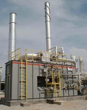
After much consideration, Anguil offered their Model 75 (7,500 SCFM, 12,037.5 Nm3/hr) Regenerative Thermal Oxidizer (RTO) with heat recovery for efficient and effective operation. Anguil was selected because of their unique approach toward air pollution control and energy conservation.
With the Anguil two-bed RTO, the contaminated process gas is pre-heated as it passes through beds of ceramic media located in the energy recovery chambers. The process gas moves from the pre-heat chamber toward the combustion chamber, where the Volatile Organic Compounds (VOCs) are oxidized, releasing energy into the second energy recovery chamber before going to atmosphere. A diverter valve switches the process gas direction so both energy recovery beds are fully utilized, thereby reducing any auxiliary fuel requirement. This system is designed for heat recovery of 85% and is self-sustaining, requiring little auxiliary fuel use. This energy-efficient design offers significantly lower operating costs in comparison to other emission treatment methods.
The RTO is designed to prevent corrosion by the acid gases and to handle the high organic loading with low oxygen levels. The gas at this facility is “sweet” and does not contain any H2S but precautions were taken to prevent carbonic acid attack due to the CO2. In addition, Anguil provided a Class 1, Division 2, Group D control package. Heated, fresh air was also introduced into the system, providing supplemental oxygen without condensing moisture in the process stream. Anguil’s application specific engineering was an important factor in the success of this project.
The Anguil RTO is achieving 99% DRE (Destruction Rate Efficiency) and is saving the customer more than $500,000 per year in natural gas costs. Anguil’s equipment, detailed system design, installation and startup has exceeded the customer’s expectations of efficiency and affordability.
Amine Tail Gas Treatment
Comments Off on Amine Tail Gas TreatmentTHE CHALLENGE
With the discovery of new shale formations throughout the world, and the development of new drilling technologies, natural gas production has increased. The rise in production has prompted government agencies to initiate tighter air-pollution control regulations on processing operations. Sustaining environmental regulations is not typically a profit-generating endeavor. As a result, saving money while meeting regulations should be every midstream company’s priority.
Much like other industries, oil and gas producers are often required by the Environmental Protection Agency (EPA) to obtain a Title V permit. Title V’s objective is to prevent untreated air pollutants from entering the atmosphere. In addition to their harmful effects on the environment, these pollutants, known as volatile organic compounds (VOCs) and hazardous air pollutants (HAPs) have been linked to respiratory ailments, heart conditions, birth defects, nervous system damage, and cancer in humans.
Under the Clean Air Act, most companies with the potential to release more than 10 tons of a single VOC or HAP during a one-year period, or 25 tons of multiple compounds, must install either a pollution-control device. Many of the pollution control devices currently used to abate these emissions also emit significant amounts of carbon dioxide (CO2) and nitrous oxides (NOx). With mandatory greenhouse gas (GHG) reporting on the horizon, processors could soon be paying for the carbon emissions generated by some of these pollution control systems, adding to the capital and operating costs associated with regulatory compliance.
Several production techniques and processes used by midstream companies are, or soon will be, regulated as emission sources. From stationary combustion engines to amine systems, the industry is facing strict legislation.
The midstream division of a large, multinational energy corporation was operating several amine systems around the country with tail-gas treatment. A thermal oxidizer (TO) at one of these facilities had numerous operational problems and extremely high operating costs.
Amine tail-gas treatment is one area of great legislative concern in the industry. Amine systems are a very common and critical component used by natural gas-processing facilities to remove acid gases, carbon dioxide (CO2), and hydrogen sulfide (H2S). This is accomplished by running the gas through a column with amine liquid flowing in the opposite direction, stripping acids from natural gas and absorbing them into the liquid. The natural gas is then sent for processing while the amine is sent to be regenerated. The regeneration process removes the acid gases from the amine solution, allowing it to be reused, but the process creates tail gas. This tail gas, and the means for treating it, offer the latest opportunity for the implementation of new technologies and increased profits.
Thermal and catalytic oxidizers are technologies commonly used on a wide variety of applications where VOC, HAP, and odor abatement is required. They destroy harmful emissions through the process of high-temperature combustion. Midstream companies have historically used flares, vapor combustors, direct-fired thermal oxidizers (DFTOs), or recuperative systems for emission destruction. Applications where these devices are applied range from amine tail-gas treatment, nitrogen rejection units, and liquefied natural gas (LNG) processes. The temperature in these systems is maintained somewhere between 1,400°F – 1,800°F (760°C – 982.2°C) so that hydrocarbons are converted to CO2 and water vapor, while the H2S is converted to sulfur dioxides (SO2 and SO3).
When designed properly these older technologies are dependable, but their effectiveness sparks heated debate. In the case of flares, water is often injected into the device to reduce visible black smoke. This drastically reduces the destruction efficiency — and the EPA is taking note. Large amounts of fossil fuels are required to bring the air toxins up to proper destruction temperature. Rather than use the heat generated from combustion to preheat incoming pollutants, the energy is simply released into the atmosphere, along with GHGs.
A proven fuel-efficient abatement technology called the regenerative thermal oxidizer (RTO) is now being applied to tail-gas treatment where it was once thought impossible. What differentiates it from other technologies is its ability to use the proper mix of temperature, residence time, turbulence, and oxygen to convert pollutants into carbon dioxide and water vapor. The system reuses the thermal energy generated to further reduce operating costs. In some cases, emission destruction can occur without any additional natural gas or other supplemental fuel.
VOC- and HAP-laden process gas is routed into the inlet manifold of the oxidizer, flow control, or poppet valves. These valves then direct this gas along with fresh air for combustion into energy-recovery chambers where it is preheated. The process gas and contaminants are progressively heated in the ceramic media beds as they move toward the combustion chamber.
Once oxidized in the combustion chamber, the purified acid gas releases thermal energy as it passes through the media bed in the outlet flow direction. The outlet bed is heated, and the gas is cooled so that the outlet gas temperature is only slightly higher than the process inlet temperature. Poppet valves alternate the airflow direction into the media beds to maximize energy recovery within the oxidizer.
Thermal energy recovery (TER) within an RTO can reach 97%, which in some cases eliminates the auxiliary fuel requirement. Some gas plants have reported over $500,000 in operating cost savings annually. With destruction capability over 99%, the RTO is an efficient alternative for this application. However, careful consideration must be given to the design and materials of construction to avoid corrosion, equipment failures, non-compliance, and safety issues.
THE SOLUTION
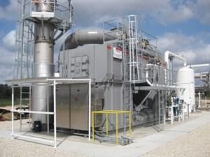
The company asked Anguil Environmental Systems to evaluate replacement options. The process data provided showed a tail-gas flow rate of about 15,000 lbs/hr or about 2,500 SCFM (4012.5 Nm3/hr). After evaluating numerous oxidizer technologies, including TOs and thermal recuperative oxidizers, Anguil determined that the best solution would be an RTO. Having designed oxidizers for similar corrosive applications, the engineers at Anguil recommended the RTO be built with special materials and design considerations to combat the presence of both carbonic and sulfuric acid.
Carbonic acid is caused by high CO2 levels combined with a saturated process stream. Sulfuric acid is created when H2S is oxidized and the resulting SO3 combines with water vapor present in the RTO exhaust gas. The amine process exhaust at this midstream operation was inert, or lacking oxygen; therefore, fresh air was required for oxidation. Heat released from combustion of these hydrocarbons can be very high, so fresh air is also added to keep the system from running over temperature. To eliminate condensation of water vapor of the tail gas inside the RTO, this ambient air is preheated to protect metal surfaces from inorganic acids condensing.
THE RESULT
A system utilizing excess heat from the combustion chamber to provide the necessary heat was deployed on this system, further reducing operating costs. The preheat component eliminates the need for additional equipment and further minimizes auxiliary fuel consumption. The next step in the corrosion-protection strategy is to implement various stainless-steel alloys on critical components and a corrosion-resistant coating on the inside of the energy-recovery and combustion chambers.
The critical components are chosen based on their function within the RTO. These components see exhaust temperatures of up to 600°F (315°C), above the limit of corrosion-resistant coatings. The energy recovery and combustion chambers are internally insulated with soft ceramic refractory insulation, limiting the shell temperature to 200°F (93°C), well below the safe limit of the coating. With the combination of extremely high TER, and the tail-gas calorific value of 6 Btu/SCF, this RTO requires no auxiliary fuel to achieve 99% destruction efficiency.
Protecting the environment, meeting regulations, and saving money are not mutually exclusive. Re-evaluating, and upgrading abatement technology should be a priority for every industrial manufacturer.