


Catalytic Oxidizer Catalyst Replacement
Comments Off on Catalytic Oxidizer Catalyst Replacement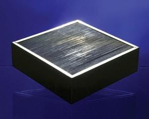 The Challenge
A New Jersey pharmaceutical company purchased a thermal incinerator to treat the heptane and hexane exhaust from their capsule wash system. The thermal incinerator’s “tubular” design was modified with a catalyst bed in order to reduce the system’s operational costs. Unfortunately, when operating in the catalytic mode, the oxidizer failed to provide the required 95% destruction efficiency of non-methane hydrocarbons required by the New Jersey Department of Environmental Protection. These odorous emissions led to neighbor complaints and an EPA consent decree, complete with a $175,000 civil penalty. Although the company was proactive in trying to solve the emission problem, the EPA stipulated penalties of $2,500 for every day the violation existed. The original equipment supplier attempted to rectify the problem to no avail and the pharmaceutical company remained in violation of their New Jersey air permit.
The Solution
After meeting with several potential suppliers, the company selected was Anguil Environmental Systems, Inc. Anguil’s track record with catalytic systems, knowledge of catalyst and engineering strength made them the most likely candidate to tackle the VOC problem successfully.
 The Result
 The Result
Anguil successfully retrofitted the non-compliant system and brought the company into EPA compliance. The first step in Anguil’s approach was to examine the reason for catalyst nonperformance. There were several potential reasons for catalyst failure. The possibility of catalyst masking or the presence of a poisoning agent (i.e. sulfur, phosphorus, heavy metals) within the VOC-laden stream was examined; however, no significant levels of any of these agents were detected.
The second possibility was that the industrial process stream was being allowed to pass through the oxidizer before it was brought to proper operating temperature. This would result in the coating of the stainless steel rings with the heptane and hexane hydrocarbons. If this was the case, when the unit was brought to the proper operating temperature, oxidation would occur on the catalyst, leaving a carbon deposit. This type of carbon deposit would result in decreased destruction efficiency and the formation of incomplete combustion products. No signs of these carbon deposits, known as coking, were detected.
Having eliminated these suspects, Anguil conducted a laboratory performance test that indicated the reason for catalyst failure: the catalytic stainless steel rings lacked the proper surface area to achieve the quoted destruction efficiency. This performance test revealed that there was less than 50% destruction efficiency of a propane and propylene test stream. This is an excellent indicator of catalyst failure or inactivity.
Anguil modified the system design to accommodate a honeycomb catalyst. The monolithic catalyst Anguil chose was a 300 cell-per-square-inch ceramic substrate. An alumina washout was used to deposit large quantities of precious metal (i.e. platinum, palladium, rhodium). The surface area of this replacement catalyst is more than 100 times greater than that of its stainless steel counterpart. (Note: a cubic foot of this monolithic catalyst contains more surface area than that of a football field.) The oxidizer was equipped with a new reactor section to house the nine cubic feet of monolithic catalyst. A 95% destruction efficiency guarantee was provided along with the system retrofit.
A follow-up Flame Ionization Detector (FID) was also performed on this retrofit and a carbon filter was added to eliminate methane readings. The FID test results indicated a VOC inlet concentration of 943 ppm and an oxidizer outlet concentration of less than 20 ppm. The company is now EPA-compliant 97.8% destruction efficiency. Anguil is well-known for providing VOC control systems but in this case, they demonstrated their ability to provide answers where others had failed.
RTOs Leave Nothing Hap-Penstance
Comments Off on RTOs Leave Nothing Hap-Penstance The Challenge
 The Challenge
The United States EPA promulgated a ruling in 40 CFR, imposing strict new standards to reduce emissions of toxic air pollutants from the manufacture of pharmaceutical products, including prescription and over-the-counter drugs. The agency’s rule was intended to reduce emissions of a number of air toxins and hazardous air pollutants (HAPs), including methylene chloride, methanol, toluene and HCI. It was estimated at the time that the ruling would reduce air toxins annually by approximately 24,000 tons or 65 percent from contemporaneous levels. The affected pharmaceutical manufacturing processes included chemical synthesis (drawing a drug’s active ingredient) and chemical formulation (producing a drug in its final form).
The Solution
One of the approximately 100 facilities affected by the ruling was a pharmaceutical plant in upstate New York. Determined to stay below acceptable MACT levels, the company set out to establish compliance needs and subsequent direction by contracting with a consultant to formulate a compliance plan. The result was a specification package that required oxidation and caustic scrubber technologies.
 The Result
 The Result
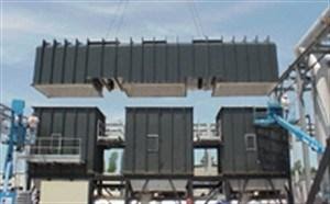
Specifically, the design included a primary and backup system, each consisting of two 35,000 SCFM (56,175 Nm3/hr) regenerative thermal oxidizers (RTOs) and two 35,000 SCFM (56,175 Nm3/hr) caustic scrubber systems. The RTOs were to process the emissions, including methylene chloride, acetone, ethanol, isopropyl, alcohol, methanol and mineral spirits, and were designed to achieve over 99-percent destruction efficiency. The scrubbers were designed to process treated gases and achieve 99.5-percent reduction of the HCI derived from the oxidation process. After the design phase, the two technologies were selected in order to oxidize the VOC/HAP compounds, and to remove the resultant HCI emissions from the outlet of the oxidizer. Upon receipt of the specification package, the engineering staff at Anguil began to design the system within the boundaries of the specifications.
The specification package included the following requirements and parameters:
Process producing emissions – multiple (~60) sources including:
- Conservation vents
- Reactor vents
RTO materials of construction:
- Refractory selection: The RTO included the installation of high-purity ceramic fiber insulation, because of its resistance to HCI attack.
- Purification chamber outer skin: The purification chamber was constructed of 0.25 inch A36 Steel. It was internally blasted and coated with a vinyl ester corrosion-resistant coating. This coating resists any HCI (vapors or condensed acid) that could potentially reach the RTO shell behind the insulation. The coatings were pigmented so that the first coating was light gray and the second coat was dark gray. This allowed a visual inspection to identify that the coating was thoroughly applied during fabrication, and provides an easy means of checking for coating degradation after operation.
- Ceramic media support grid: The ceramic media support grid was constructed from Hastelloy C276 in order to support the ceramic media. This “cold face” has the potential too see condensed acid gas. Hastelloy C276 provides high strength and resists both chloride stress corrosion cracking and chloride pitting and crevice corrosion.
- Inlet plenum: The inlet plenum is the duct located underneath the RTO that connects to the three inlet butterfly diverter valves. The air flowing through this duct to the RTO contains VOCs and HAPs but does not contain acid gases. However, as a precaution against corrosion, this ductwork was constructed of AL-6XN, a corrosion resistant alloy.
- Outlet plenum: The outlet plenum is the duct located underneath the RTO that connects to the three outlet butterfly diverter valves. The air flowing through this duct to the RTO contains acid gases. This ductwork was constructed of Hastelloy C276.
- Bed/plenum/hopper: The plenum beneath each of the three ceramic media support grids was constructed of Hastelloy C276.
- Butterfly valves (bed inlet, outlet and purge): The three inlet diverter valves process air containing VOCs and HAPs. The three outlet diverter valves contain air containing acid gas. All sic valves were constructed of Hastelloy C276. The three purge valves were also constructed of Hastelloy C276.
- Transition to acid gas scrubber quench: The transition from the RTO outlet plenum to the acid gas scrubber quench contains acid gases. This ductwork was also constructed of Hastelloy C276.
Floor sweeps:
- Waste stream flow rate: 6,500-35,000 SCFM (10,432.5-56,175 Nm3/hr)
- Waste stream temperature: 50 to 100ºF
- VOC/HAP breakdown
The company possessed a long history treating halogenated compounds, including oxidation and acid gas scrubbing equipment. The two RTO and scrubber systems supplied here were actually installed after a smaller oxidizer and scrubber was operational within the same facility.
General Operational Description
Designing the oxidizer first, engineers specified that each RTO would process up to 35,000 SCFM (56,175 Nm3/hr) of VOC/HAP-laden air, providing 99.5% destruction efficiency.
Pharmaceutical Industry Pollution Control Solutions
The oxidizer consisted of three reinforced, insulated, steel chambers filled with high-temperature, structured ceramic energy recovery media. Each oxidizer would utilize two burners to maintain its oxidation temperature set-point, and provide even temperature distribution within the combustion chamber for maximum VOC/HAP destruction. Located below each of the energy recovery chambers would be inlet and outlet diverter valves and the associated air duct plenum passages. These would allow the process airflow to be diverted into and out of each of the heat recovery chambers. One duct would act as an inlet to the energy recovery chamber, the other as an outlet from the chambers to the acid gas scrubber. A third, smaller duct would direct heated purge air to each chamber. A purge valve for each chamber would control the flow of purge air into the chamber. The directional mode and purging would be controlled by a PLC program, which would change the direction of airflow at regular intervals to optimize system efficiency. The typical flow directions within the RTO would be adjusted every 90 seconds.
In operation, solvent-laden air (SLA) would enter the oxidizer via an energy recovery chamber, where the high-temperature ceramic heat transfer media would rapidly preheat it prior to its introduction into the oxidation chamber. After the chemical oxidation purification reaction occurs, the hot, clean, outgoing gas would heat the exit energy recovery chamber.
The SLA flow direction would be switched at regular intervals to maintain optimum heat recovery efficiency by the automatic diverter valves on demand from the PLC control system. After serving as an inlet, an energy recovery chamber would be purged for a cycle before serving as an outlet. This ensured that all air that entered a bed would be treated to the maximum extent possible. With sufficient concentration of hydrocarbons would self-sustain the oxidation process. The oxidizer can be operated in an off-line bake-out mode to allow the removal of organic buildup on the heat exchange media. The potential organic material consists of methylcellulose and lactose. In the bake-out mode, the RTO/scrubber trains are taken offline from the process. At a reduced airflow, the outlet temperature is allowed to rise before the flow direction is switched. This hot air vaporizes organic particulate collected on the cold face of the heat exchange media. The flow direction is switched and other cold faces are cleaned in succession.
Process Air Flow
Two 35,000 SCFM (56,175 Nm3/hr) systems were specified to provide redundancy while processing flows from 6,500 SCFM (10,432.5 Nm3/hr) to 35,000 SCFM (56,175 Nm3/hr). Each RTO/scrubber train would be functionally equivalent and operate in conjunction with or independent of each other. Each system could be returned down 6:1 (5,850 SCFM, 9,389.25 Nm3/hr). If the airflow to an individual RTO/scrubber was reduced below this level, a pressure control loop could open the fresh air damper to maintain the minimum system airflow. Butterfly isolation dampers were included at the inlet and outlet of each RTO/scrubber. The inlet isolation damper would be used to isolate an RTO/scrubber train during startup and shutdown. The outlet isolation damper would be activated when the RTO/scrubber was not in use. Butterfly isolation valves were included downstream of the scrubber; the manually operated valves would be used to isolate the RTO/scrubber train for service. A flanged blind was also included for installation downstream of the scrubber for isolation during service.
Fan Location
The RTO processes corrosive HCI vapors as the chlorinated hydrocarbons are oxidized. In a forced draft arrangement, the RTO is under positive pressure. In that configuration, the corrosive gases will tend to leak to atmosphere at the instrumentation (thermocouple) penetrations and the corrosive gases will condense at this interface corroding the outer shell. Therefore, an induced draft arrangement is typically preferred for chlorinated RTO applications. A fan was designed for the conditions at the scrubber outlet, including a radial blade fan wheel constructed of a corrosion resistant alloy, Hastelloy C276, and a carbon steel housing lined with rubber. This type of fan wheel was not as efficient as backward inclined or air foil designs, but it would not be as sensitive to aerosol droplets and offered a lower tip speed, reducing fan noise.
99.5% Destruction Efficiency Design
A residence time of two seconds at 1650°F was proposed to achieve an average destruction efficiency of 99.5 percent. Actual compliance test data demonstrated destruction efficiency in excess of 99.9 percent. In order to guarantee the high destruction efficiency that this project required, additional steps were taken to reduce the air not fully treated when the airflow changed direction. For the 99.5-percent destruction guarantee, the system was designed with three chambers. At any one time, one chamber would act as an inlet and one as an outlet, while the third was being purged. After serving as an inlet chamber, each chamber would be purged with heated clean air during the next cycle. The purge air would be heated to minimize the potential for HCI gas water vapor condensation and the resultant corrosion potential, even though high nickel and molybdenum alloys were used to resist corrosive effects. It would then become an outlet chamber during the next cycle. The three-chamber design also minimized any inlet/outlet bypass during valve cycling.
Acid Gas Scrubber
The acid gas scrubber was designed to process the maximum exhaust capacity of the RTO exhaust, including the purge air containing HCI vapor, providing 99.5-percent HCI removal. The horizontal quench was designed to cool the RTO exhaust to approximately 150°F. The re-circulation pumps provided water into the adiabatic quench through three separate spray headers. The air temperature was reduced to 150°F at the quench outlet. The water that was not evaporated flowed to the recycle sump. Approximately 50 percent of the HCI was scrubbed in the scrubber quench. The air left the horizontal quench and entered the bottom of a counter-current packed tower scrubber. Water and caustic solution was sprayed on the top of the tower. The remaining acid gases were absorbed by the solution as the air passed up the column. The air passed through a mist eliminator to remove entrained water before exiting the scrubber column. A sodium hydroxide solution was added to the re-circulating water to neutralize the adsorbed HCI and form sodium chloride (salt water), the sodium hydroxide addition rate controlled by pH analyzer. Salt water blow-down was controlled by a conductivity analyzer and by adding makeup water, causing sump overflow. The company worked closely with the customer and the consultant throughout the bid process, suggesting options and clarifying details on this major environmental project, and was also commissioned to install the systems. A tight site location necessitated the careful use of over-sized cranes so as to ensure no interference with or rupture of critical plant gas, air and nitrogen lines. Heavy rains throughout much of the process further complicated installation but ultimately the installation of all the equipment and the tie-in of the ductwork, electric and controls, without affecting process, were achieved. The result was a system, which surpassed the customer’s objective of 99.5 percent destruction efficiency and ensured compliance with the EPA’s pharmaceutical MACT.
ETO Sterilizer Abatement
Comments Off on ETO Sterilizer Abatement The Challenge
 The Challenge
Product sterilization companies are generally required to utilize a pollution control device, often referred to as an abator, for treatment of exhaust gases from their aeration rooms, sterilization chambers and vessels. In the United States, they need to be in compliance with NESHAP (National Emission Standards for Hazardous Air Pollutants) regulations that dictate a 99% destruction efficiency of EtO (Ethylene Oxide), or concentration levels below one part-per-million by volume.
One contract sterilization company was using a wet scrubbing system that was no longer a viable means of EtO removal. To further complicate the situation, their high production levels meant they could not afford a factory shutdown in excess of eighteen hours. This time limitation made the procurement of a pre-tested, pre-assembled pollution control system a necessity.
The Solution
After examining various technology alternatives and multiple suppliers, the sterilization company chose Anguil Environmental Systems to provide a catalytic oxidizer that would result in NESHAP compliance and minimal downtime.
A back-vent and peak shaver were also considered upstream of the oxidizer to prevent emission spikes from causing an upset condition. However, a detailed application analysis showed it was not necessary on this particular application.
The Result
Having experience with ethylene oxide emissions and sterilizer applications, Anguil recognized several unique challenges associated with this project. First, the catalytic oxidizer had to control both the high concentration, low air volume exhaust from the sterilization chamber’s vacuum pump, as well as the low concentration, high volume exhaust from the aeration room. The high concentration from the vacuum pumps of nearly 300,000 parts per million by volume caused a sharp temperature increase, and demanded that the catalyst have a large operational temperature window. At the same time, the catalyst needed a low operational temperature when treating the low concentration exhaust (10 parts per million by volume) from the aeration chamber.
To satisfy both these needs, Anguil, in conjunction with their catalyst supplier, performed extensive research and was able to supply a base metal type catalyst with an operational temperature of 275°F and an operational temperature window of over 500°F.
On some sterilizer installations, the highly concentrated chamber emissions present another set of challenges. Because they generally come in spikes when the chamber is evacuated, Anguil often recommends and installs a peak shaver or wet-scrubber upstream of the oxidizer as a safety precaution. Safety is always a priority on Anguil oxidizers. This buffer before the combustion device alleviates any concerns of property damage or personal injury.
The next challenge Anguil faced for this application was designing and building a system that not only met NESHAP regulations, but would also operate cost-efficiently. Due to stringent ethylene oxide regulations, catalyst bed bypassing had to be completely avoided. To facilitate this, Anguil altered their traditional design and placed the base metal catalyst in horizontal tray configurations. This minimized the bypassing concerns associated with air passing around the catalyst media or bed.
To keep operating costs down and prevent leakage that could result in a comingling of the clean and dirty air streams, a 65% effective 304L stainless steel leak-and-dye tested shell and tube heat exchanger was used in the oxidizer. Unlike other manufacturers who recommended a plate type heat exchanger, Anguil was able to guarantee 0% leakage of VOC-laden air into the clean air stream. As a fail-safe, Anguil installed an induced draft fan on the catalytic oxidation system. By placing the fan on the discharge side of the oxidizer rather than placing it on the inlet side, the system was under a continuous negative pressure. This meant that any leakage associated with the oxidation system would be released back into the system, rather than out into the work environment.
The entire interior reactor of the oxidizer was constructed of 304L stainless steel, surrounded by mineral wool insulation and an outer aluminized steel frame. This unique design offers multiple benefits, including increased equipment life compared to the industry-standard aluminized steel reactor interior. Another accommodation Anguil had to consider was the customer’s time restrictions due to high production levels. Anguil’s solution was to completely pre-assemble, pre-wire and pre-test the system prior to shipment. The customer’s 18-hour time restriction was met with time to spare.
Controlling Pharmaceutical Coating & Drying Process Emissions
Comments Off on Controlling Pharmaceutical Coating & Drying Process Emissions The Challenge
 The Challenge
Originally published in Tablets & Capsules Magazine
Capturing and destroying harmful emissions from pharmaceutical processes can be challenging. It’s not because the volatile organic compounds (VOCs) are difficult to destroy using catalytic or thermal techniques. It’s because their concentrations can be so high. These process streams raise safety concerns, both when they’re collected in vents and when they reach the final combustion equipment. This article discusses the options.
Catalytic and thermal oxidation are the two best technologies for destroying VOCs in emissions from pharmaceutical and other operations. Both use high-temperature combustion to break down pollutants, leaving only carbon dioxide (CO2), heat, and water vapor. Pharmaceutical operations, however, typically require customized emission control systems to handle the high VOC concentrations that emanate from tablet coating, fluid-bed processing, and tray drying. Often the concentrations reach the explosive range, which means the emissions must be diluted before they’re introduced to an oxidizer to ensure a safe operation that protects employees and property.
The Solution
Process background
Today, most tablet coatings are aqueous, but many pharmaceutical manufacturing operations still use VOCs such as ethanol and isopropyl alcohol (IPA). This includes the manufacture of active pharmaceutical ingredients (APIs) that are dissolved in VOCs and then spray-dried to create an amorphous solid or granules. Most of these processes are batch operations, and that leads to significant and nonlinear VOC concentrations in their exhaust. In fact, the VOC concentration often exceeds the lower explosive limit (LEL) by 100 percent. In the presence of an ignition source and sufficient oxygen, these process exhausts—if not mitigated—will lead to an explosion.
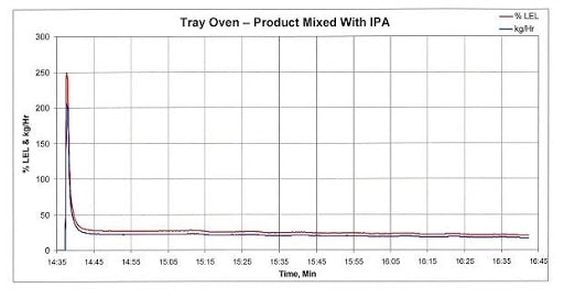
Figure 1 below tracks the emissions and LEL concentration of the exhaust from a fully loaded tray dryer that was measured after heat was applied to drive off the VOCs. Approximately 30 seconds after heat was applied, the IPA concentration peaked at approximately 250 percent of LEL. If this stream was delivered straight to an oxidizer operating at high temperature, there would be an explosion. About 8 minutes after spiking, the VOC concentration decreased to approximately 25 percent of LEL, which is the acceptance limit of most standard equipment that treat VOCs using catalytic or thermal oxidation.
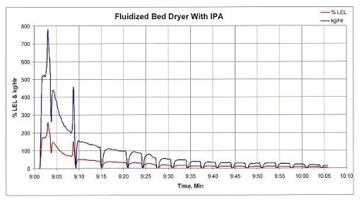
Fluid-bed processors can generate the same peaks, as Figure 2 shows. In this case, the processor’s inlet air temperature is 40°C for 20 minutes and then remains at 45°C until the end of the production run. Following the initial product transfer into the fluid-bed dryer, the exhaust concentration reached an initial peak concentration of approximately 370 percent of LEL. Approximately 6 minutes later, a second VOC spike occurred after the process bowl was scraped. This second spike resulted in a peak concentration of about 200 percent of LEL. These exhaust concentrations, with an ignition source and sufficient oxygen, would result in an explosion.
Vent collection and oxidizer control software
In short, the data tell us that you should expect high VOC concentrations in emissions from coating, fluid-bed, and tray drying operations. There are two common ways to manage the peaks, mitigate the risks, and operate safely. The first is vent control software that recognizes when processes or batches are ready to start. It then “reserves space” for them in the vent collection system. The second method uses software in the oxidizer’s control system to identify how many processes are running. It then allows only one new process to come online to the oxidizer and only during a specific period.
The vent collection software puts you in communication with operators or links to automatic controls at each stage of production, signaling when it’s safe to come online and when to wait. If multiple demands to vent arrive at the same time, the software delays new batches and processing until it learns that exhausts from earlier batches are well beyond peak VOC concentration.
This control method uses the dilution capacity of existing process exhaust points—beyond their peak concentrations—to verify safe status and allow a new batch. If no processes are online to the oxidizer and a batch start is requested, then the software must verify that enough fresh dilution air is available. This software can also verify that sufficient fresh air is available to process several batches in quick succession, maximizing production.
The oxidizer control software works in the system’s PLC-based controls to communicate with operators or equipment to signal when more processes can come online. It could require, for example, a minimum number of processes to be online to the oxidizer for a certain period. That would indicate that the VOC concentrations are beyond the peak and a new source can come online. The software can also verify that a minimum amount of fresh air is sent to a new production source to dilute the exhaust before it reaches the oxidizer.
Even with this software installed, additional safety provisions for emission control would likely be incorporated following a plant-wide process hazard analysis (PHA). They would likely include LEL high-limit switches to prevent a dangerous concentration from entering the oxidizer or abatement device. Ideally, these LEL devices would be self-calibrating to minimize expenses and respond very quickly. A PHA would also show where to install LEL controls in relation to the process-exhaust and oxidizer-isolation dampers. Often, flame or detonation arrestors are placed in each process-exhaust line to mitigate damage to the processes if all other safety measures fail.
 Emission control methods
 Emission control methods
Catalytic oxidation
VOC emissions from many pharmaceutical coating and drying processes have historically been controlled with catalytic oxidation. The process is similar to how automotive catalytic converters treat exhaust. Process emissions pass through a catalyst that allows lower oxidation temperature to destroy the VOCs. Because the process emissions—often alcohols and/or acetone—are very catalyst-friendly, catalytic oxidation can remove VOCs at high rates. However, in contrast to automobile exhaust, these industrial emissions are at a low temperature and must be heated to activate the catalyst so it can oxidize the VOCs. Typically, this is done using the oxidizers gas-fired burner, often in conjunction with integral heat recovery to reduce fuel consumption. Recovering this thermal energy—typically at rates of 65 to 70 percent—also reduces the amount of CO2 emitted into the atmosphere because the system is more energy efficient and depends less on auxiliary fuel-fired burners.
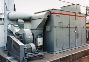
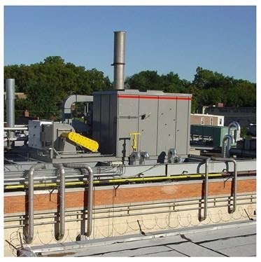
The photo below shows an integrated catalytic oxidation system that incorporates the catalyst, integral heat exchanger, gas-fired auxiliary heat system, system fan, and a PLC-based control panel. This equipment controls the emissions from 12 pharmaceutical coating pans and tray dryers, as well as VOCs from an air stripper’s exhaust.
Although catalytic oxidizers have been used successfully in the pharmaceutical industry for many years, other control technologies have gained appeal because they can treat larger exhaust volumes more efficiently. Abatement equipment is also being used to control VOCs from more sources, which increases emission volume and the need to dilute emissions to safe LEL levels. The abatement equipment thus grows in size. In order to reduce costs, companies are opting for fewer but larger abatement devices.
Regenerative thermal oxidation
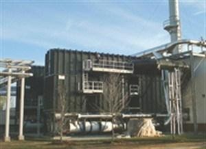
Like other industries where abatement equipment volumes have increased over time, the pharmaceutical industry is witnessing a shift from catalytic oxidation to regenerative thermal oxidation (RTO). RTO uses high-temperature combustion (with little supplemental fuel) to break down pollutants, converting them into small amounts of CO2, heat, and water vapor. Specifically, the process gas and contaminants are progressively heated as they move through insulated chambers filled with ceramic media. Once oxidized in the combustion chamber, the hot, purified air releases thermal energy as it passes through a second media bed in the outlet flow direction. Valves alternate the airflow direction into the media beds to maximize energy recovery within the oxidizer. The outlet bed is heated and the gas is cooled so that its temperature at the outlet is only slightly higher than it is at the process inlet. This greatly reduces the need for auxiliary fuel, which lowers operating costs.
RTOs can also provide very high VOC oxidation efficiency but do so at higher combustion chamber temperature without the need for catalyst to maintain that temperature. Even at RTO’s higher operating temperatures, auxiliary fuel usage can be lower compared with catalytic oxidation because RTOs energy recovery and thermal efficiency are generally 95 percent but can reach values as high as 97 percent. Thus, auxiliary fuel consumption and the resulting CO2 emissions to atmosphere are lower with an RTO device than they are with a catalytic oxidizer.
Larger air volumes also argue in favor of RTO devices because they are generally built of carbon steel. That reduces their cost compared to catalytic oxidizers, which not only incorporate precious metal catalysts, but are also primarily built of stainless steel. (RTO devices that handle halogenated VOCs are built using higher-cost alloys to resist acidic gases.) While RTO devices are replacing catalytic oxidizers in many cases, the selection depends on the application. One drawback of RTO is that the equipment is much heavier, which reduces installation options.
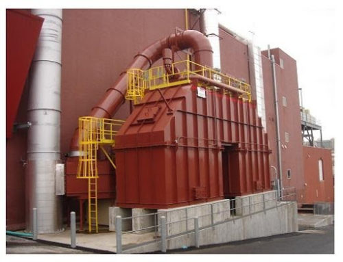
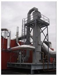
The photo below shows an RTO system Installed at a pharmaceutical plant. It controls emissions from four tray dryers, 13 fluid-bed dryers, and three coating pans. Much like the catalytic oxidizer shown above, the system incorporates LEL controls to verify a safe operating system. Because it’s located in a cold-weather area, any dilution air that’s added is heated to minimize the chance that water or VOCs will condense within the abatement system.
 Wet scrubbers
When processes emit extremely high VOC concentrations and exhaust flows are very large, dilution becomes more difficult, and the abatement system can grow quite large and expensive. In those cases, emissions that are soluble in water, such as alcohols, can be treated using a wet scrubber. The VOCs, however, will likely be transferred to a water stream for disposal, which may be an additional burden on the facility. In addition, the vapor pressure of the alcohols can be relatively high, which means that the wet scrubbers often use “once-through” water. That raises concerns about the volume of water used and how to dispose of it. Even so, this method has been used on occasion to control high concentrations of VOC (alcohol) emissions. In some instances, wet scrubbers are used in conjunction with oxidation equipment such as RTOs.
The Result
When designing abatement systems for pharmaceutical processes that involve coaters or dryers, understand the emission types, what the VOC concentrations are, and how they fluctuate during processing. Next, conduct a PHA to identify the design requirements for the abatement system to operate safely and effectively.
Once you have determined the flow and total VOC emission rate from the facility, consider all the technology options for removing the VOCs. Catalytic oxidation remains a viable technology for relatively small exhaust flow rates. RTO offers lower capital and operating costs at process exhaust flows of 5,000 SCFM (8,025 Nm3/hr) or larger. Wet scrubbers also warrant consideration, even though their high consumption of water and the need to dispose of the wastewater make it unattractive in many applications.
Air-to-Water Heat Exchanger Reduces Operating Costs by $120,000 per year
Comments Off on Air-to-Water Heat Exchanger Reduces Operating Costs by $120,000 per year The Challenge
 The Challenge
This pharmaceutical company had a 5,000 SCFM (8,025 Nm3/hr) oxidizer that they were looking to relocate to another facility across the United States. The destruction rate efficiency and heat recovery expectation at the new location differed from the original design conditions at the current facility.
The Solution
An Anguil field service engineer went to site to inspect the unit. A report detailing the current condition of the oxidizer at its current location was generated as well as a written procedure for the proper dis-assembly and reassembly of the equipment. The service engineer evaluated the unit and made recommendations outlining the modifications necessary to make the unit run at the new facility’s desired destruction efficiency rate and the energy requirements.
The Result
Anguil worked closely with the customer to modify and upgrade the system based on the detailed site inspection report. The work included a control package upgrade and a new hot gas bypass damper.
To address the energy recovery requirements at the new facility, a new economizer was installed between the oxidizer and exhaust stack to transfer heat to water. The exhaust heat from the stack was transferred to the Anguil economizer which in turn created hot water. This otherwise lost energy is captured and can be used in various applications such as boiler feedwater, cold makeup water, process water, glycol, and thermal fluids.
The stainless steel system is a tube and fin style heat exchanger with access doors for inspecting and cleaning of the tubes. The exhaust flow from the catalytic oxidizer is 5,400 SCFM (8,667 Nm3/hr) and the temperature is 450°F (232°C). Roughly 160 GPM of water is heated to 140°F (60°C) with the economizer. The total energy recovered is 1.43 MM BTU/hr or an estimated total savings of $120,512 per year.