


Superfund Site, Water Pump & Treat
Comments Off on Superfund Site, Water Pump & TreatThe Challenge
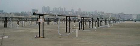
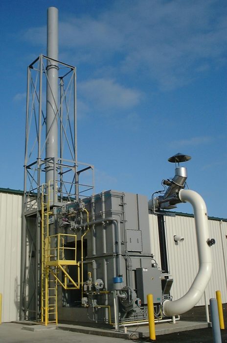
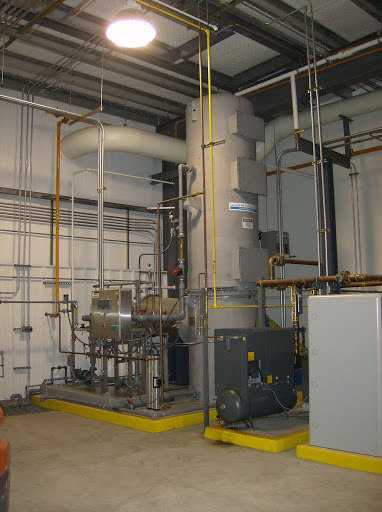
Anguil was contracted as part of a team of companies to implement a groundwater pump and treat system intended to remove trichloroethylene (TCE) from a local aquifer designated as a Superfund Site by the Environmental Protection Agency (EPA). Though the site is nestled between the buildings and roadways of 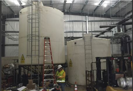 an operating industrial facility, the overall extent of the pump and treat system is expansive. Extraction wells are located over 1,000 ft. from the treatment building, with an additional 1,200 ft. of pipe run to the injection wells. All of the water treatment equipment and main control system were designed to be contained within the new treatment building, while control panels located at the extraction and injection areas were to provide local control and monitoring of the appropriate wells. Everything was to work seamlessly together.
The 500 gallon per minute (GPM) pump and treat system, as well as the overall site plan, were designed by a large engineering, procurement and construction (EPC) firm working on behalf of the responsible party. A general contractor and dedicated installation sub-contractor were selected to prepare the site, drill the extraction and injection wells, install the underground conveyance piping, erect the prefabricated treatment building, install the treatment equipment and perform all the interconnecting piping.
The Solution
Anguil was contracted for two phases of this project. During the design and approval portion, Anguil’s Electrical Engineering and Controls team was asked to review the electrical design and system controls. In addition, Anguil EEs also provided and reviewed the system controls specifications to facilitate approvals from the EPA and Army Corps of Engineers. For the construction phase, Anguil provided and managed the delivery of all the water treatment and water logistics equipment, including the control system and control panels. Furthermore, during the construction phase, Anguil field service engineers provided installation and shakedown assistance for the entire system.
Anguil’s scope of supply included all valves, process instruments and transmitters, water treatment equipment, the exhaust stack, storage tanks, pumps, chemical injection system, motor control system, main building control panel as well as two remotely located panels at the extraction and injection well sites. Further, to the largest extent possible, Anguil was directed to supply the equipment skid mounted, pre-plumbed and prewired.
The Result
Anguil was able to bring additional value to this project by successfully managing the multiple vendors of both the water treatment and controls equipment for the EPC. In particular, Anguil identified low-cost, expedited options to meet the aggressive construction schedule mandated by the EPA penalty deadlines, in some cases cutting long lead times in half. Having a custom solutions integrator on this project was especially valuable when major, unforeseen factory delays occurred. By effectively communicating with the construction team, schedules and resources were adequately adjusted. Further, Anguil was able to manage discrepancies between the selected vendor’s products and customer specifications, achieving the design specifications without sacrificing performance.
Throughout the project, Anguil provided onsite engineering assistance suggesting inexpensive changes, such as relocation of instrumentation or alternate piping plans to the equipment, which improved operations and maintenance activities. From an engineering standpoint, they were able to recommend improvements to customer specifications based on operational experience. These improvements included recommendations to upgrade materials of construction, alterations to process instrumentation, upgrading the size of the control panel touch screen to effectively display control parameters, and addition of important safety features. Furthermore, elimination of the redundant multiple control panels was accomplished by integration of logic into the Anguil supplied main system control panel. Lastly, because of site considerations, Anguil suggested substitution of the originally specified radio communications between the main control panel and remote injection well control panel with fiber optic connectivity. This ultimately resulted in a reduction of Anguil’s scope of supply, but greatly improved the system robustness and reliability.
As the project progressed, Anguil worked with the EPC engineering team on several customer-driven change orders. Most significantly, they worked with the EPC to specify and source additional flow meters for the injection well piping that were capable of accurate operation within the space constraints (limited straight run) dictated by the prefabricated concrete well vaults. Anguil managed ripple effect design changes including upgrading the effluent pump capacity, the motor control center and additional input/output cards for the local control panel – these changes were accomplished with no effect on the overall equipment delivery schedule.
In preparation of system start-up and shake down, Anguil on site personnel verified that all equipment was installed per manufacturer recommendations and was operating correctly. In several instances, they were able to identify equipment which had been installed improperly, delivered incorrectly or specified imprecisely. In most cases, these discrepancies were rectified quickly at no cost to the customer. As Anguil personnel accommodated continuing construction activities, PLC program operation was verified and altered as necessary to provide adequate system control. The final result was a turnkey system that met customer requirements for their commissioning schedule and operational characteristics so the project could start on time and on budget.
Treating Variable VOC Loadings with Hot Gas Bypass
Comments Off on Treating Variable VOC Loadings with Hot Gas Bypass The Challenge
 The Challenge
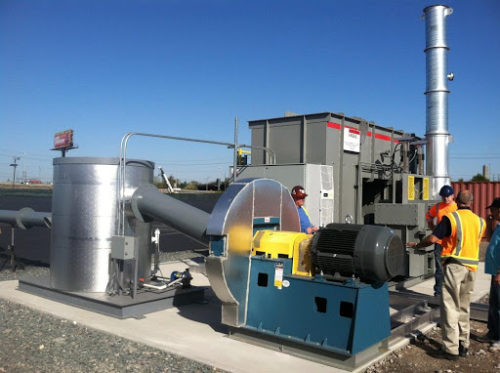
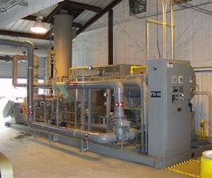
A soil and groundwater remediation firm had contacted Anguil Environmental Systems with a need to process increased Volatile Organic Compound (VOC) loading with their two Anguil Model 50 Regenerative Thermal Oxidizers (RTOs).
The Solution
The customer was experiencing high variability in VOC loading during remediation and their RTOs would shut down due to excessive temperature in the combustion chambers.
Anguil modified both RTOs to incorporate a Hot Gas Bypass, a feature designed to allow incoming process streams to have LEL levels up to 25%. HGBP diverts hot gases from the combustion chamber to the stack during high VOC loading conditions. The residence time of the diverted hot gases as they pass to the stack ensures the emissions are destroyed without affecting the system’s destruction efficiency.
Hot Gas Bypass (HGBP) is commonly ordered on new RTOs with either highly consistent VOC loading or high variability in loading. HGBP is also commonly ordered from Anguil for retrofitting onto Anguil-built RTOs and oxidizers supplied by other manufacturers.
 The Result
 The Result
Anguil retrofitted both RTOs with a new HGBP in the field. This required mechanical, rigging, and electricians onsite who were all managed by Anguil. After completion, the RTOs were able to handle the fluctuation of the customer’s process without any further high temperature shutdowns.
Quality Environmental and Energy Solutions from Anguil Environmental Systems
At Anguil Environmental Systems, we are well-equipped to provide emission abatement solutions for any industrial facility. For additional information about our capabilities and how we can benefit your company, contact us today. One of our customer service representatives will answer and address any questions or concerns you may have.
World’s Largest Remediation Site: Stepping into a Second Phase of Utilization with 21st Century Technology
Comments Off on World’s Largest Remediation Site: Stepping into a Second Phase of Utilization with 21st Century Technology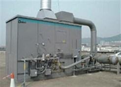
THE CHALLENGE
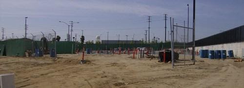
Once the world’s busiest airport, Hong Kong’s Kai Tak Airport closed its runways in 1998. When the airport was decommissioned, the government planned to rapidly clean the site for commercial and residential development. After decades of various fuels and chemicals leeching into the soil, the site required an extensive and sophisticated groundwater cleanup. A system that could destroy a minimum of 95% of the volatile organic compounds (VOCs) and minimize operating costs was necessary. Since the project generated intense government interest, and was highly publicized, the chosen treatment system had to be both proven and reliable.
After an extensive evaluation of various VOC treatment solutions, the consultant selected a system from Global Technologies, the remediation division of Anguil Environmental. With their extensive engineering support, industry-leading reliability, and history of solving difficult remediation problems around the world, Global was the clear choice. Global engineers performed a careful evaluation of the data and recommended a Model 80 Remedi-Cat ™ forced draft system. The system processes 8,000 SCFM (12,616 Nm³/hr) of VOC-laden air and provides at least 95% destruction rate efficiency.
Global Technologies’ experience with processing large air flows and irregular organic loading was crucial to this project. The proven performance of Global treatment systems provided the Kai Tak project engineers the confidence to design an innovative remediation plan. Global Technologies’ vapor treatment system was at the heart of this strategy.
THE SOLUTION
Taking an aggressive approach to remove the subsurface contaminants, the engineers installed 2,000 soil vapor extraction (SVE) wells and 1,000 sparge wells across the old airport tarmac. The vast airflow was directed from the wells to a single treatment system. This strategy provided significant savings in energy, fuel, and personnel compared to a modular approach. A modular solution would require more treatment systems to treat a limited number of wells.
Global chose a catalyst that utilizes honeycomb shape construction to provide superior airflow and low pressure drop. The catalyst selected had undergone extensive technical development, and field-testing, and was chosen to accommodate the unique airflow volume, the amount and type of VOC, and the desired destruction efficiency of the project.
Another key design feature of Global Technologies’ vapor treatment system was the variable frequency drive (VFD). The VFD controls the speed of the system fan, regulating airflow through the system and allowing the oxidizer to efficiently handle the air volume fluctuations from the 2,000-plus extraction wells. With a maximum turndown ratio of 10:1, the VFD produces energy savings far superior to an inlet vane damper. Global provided the VFD with a particulate filter and housed it in a NEMA 4 enclosure to protect it from the sun and outdoor elements.
Like all Global Technologies’ systems, the Model 80 Remedi-Cat™ was manufactured with the highest quality workmanship and construction materials. The heat exchanger and reactor were constructed of 304L stainless steel with continuous leak-tested welding around all seams. To withstand the natural elements, the exterior shell was constructed of aluminized steel with a coat of UV resistant polyurethane paint. High-density mineral wool was placed between the inner and outer shells to maintain external skin temperatures at safe levels.
THE RESULT
A final consideration was worker and equipment safety, which is a significant concern for every Global Technologies system, but is especially important on a high-profile project like Kai Tak. With safety in mind, Global developed a state-of-the-art Programmable Logic Controller (PLC) which allows safe and intelligent operation with minimal risk. The PLC provides immediate troubleshooting, first-out shutdown detection, and operator assistance for start-up. Global Technologies’ user-friendly features provide the on-site operators with more control, decreased downtime, and reduced maintenance costs.
Global Technologies’ understanding of a customer’s unique needs, coupled with the engineering know-how necessary to fulfill these needs, resulted in another satisfied customer. The cost-saving strategy of controlling numerous wells with one treatment system was made possible by Global Technologies’ ability to accommodate the large and varied airflow from the wells. Global Technologies’ aggressive and innovative treatment strategies assisted the once busiest airport move into a cleaner and safer 21st century.
Pemaco Superfund Site Remediation
Comments Off on Pemaco Superfund Site Remediation The Challenge
 The Challenge
Pemaco was formerly a chemical facility located in a light industrial and residential area of Maywood, CA, adjacent to the Los Angeles River. No one knows how long hazardous substances had been leaking into the ground but the operations date back to the 1940’s. Up until closure of the facility in 1991, chlorinated solvents, aromatic solvents, and flammable liquids had all been used in the chemical mixing, blending, storage and distribution processes at this location.
After a fire at the abandoned Pemaco location, the Environmental Protection Agency (EPA) was called in to stabilize the site and conduct an emergency assessment to determine the extent of contamination into the soil and groundwater.
The EPA worked with several environmental consultants to define a detailed remediation plan for the superfund site. It was determined that solvents and other compounds from tanks and drums caused soil contamination deeper than 90 feet. A 14-acre groundwater plume that migrated into a complex aquifer system under residential properties threatened local water supply wells with Perchloroethylene (PCE), Trichloroethylene (TCE), Trichloroethane (TCA), Dichloroethane (DCA) and Vinyl Chloride (VC).
The Solution
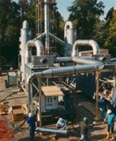
The remediation technologies used would include Electrical Resistance Heating (ERH), Soil Vapor Extraction (SVE), thermal oxidation, acid gas scrubbing and carbon absorption. The goal was to completely remediate the 1.4-acre site of these Volatile Organic Compounds (VOCs) and redevelop it as a public park. The vapor treatment portion of the project combined ceramic core flameless thermal oxidation (FTO) with acid gas scrubbing, vapor conditioning, and a carbon adsorption polishing step to control potential dioxin emissions.
 The Result
 The Result
Working with several environmental engineering firms and the US Army Corp of Engineers, Global Technologies supplied a 1,000 SCFM (1,605 Nm3/hr) Flameless Direct Fired Thermal Oxidizer (DFTO) with a caustic scrubber for emission treatment from the SVE units. The vapor treatment system was designed to handle typical averages of 315 parts per million (ppm) but capable of maximum spikes up to 25,000 ppm.
The oxidizer was designed to achieve 99.9% destruction of hydrocarbons with a unique gas-fired burner that generates virtually no nitrogen compounds (NOX) during combustion. The patented surface combustion technology ensures that all emissions are exposed to the high temperature zone only along the innermost surface. Another important advantage of this arrangement is that hot combustion gases are completely contained within the burner and the oxidizer outer shell remains cool. Therefore the flameless oxidizer can be processing toxins in a matter of seconds after ignition.
A gas flow control valve was integrated to reduce operating costs. By reducing gas flow as the energy content of the VOCs increases the oxidizer uses less supplemental fuel for combustion. It operates in response to control signals from a thermocouple located immediately downstream of the oxidizer burner.
Downstream of the oxidizer, exhaust gases flow into the integral scrubber quench chamber via Fiberglass Reinforced Polymer (FRP) ducting. Adjacent to the oxidizer, the skid mounted scrubber uses polypropylene packing to treat the acid gases. It was optimized to reduce the water usage without sacrificing spray coverage and the design allowed for a max HCl loading of 472 lbs/hr.
The flameless DFTO and scrubber were arranged in an induced draft configuration, pulling exhaust through the system and keeping it under negative pressure to prevent the escape of any corrosive gases.
The United States EPA filmed a documentary about the Pemaco remedial action for internal training purposes. The documentary highlights several “firsts” for the EPA including the use of a flameless thermal oxidizer for vapor treatment. More information can be found on the EPA website.
Mobile Remediation System
Comments Off on Mobile Remediation System The Challenge
 The Challenge
A large consulting and contracting firm owns and operates several ex-situ Thermal Desorption Units (TDUs). Each single-load unit has the capacity to desorb 15 tons of soil per hour at a temperature of 400°F – 900°F (204°C – 482°C). These TDUs have been designed to operate on both chlorinated and non-chlorinated contaminants. They are also approved for use under the Resource Conservation and Recovery Act (RCRA) and Comprehensive Environmental Response, Compensation and Liability Act (CERCLA) as well as private industry sites. Since each TDU has the flexibility to operate on standard hydrocarbon and halogenated hydrocarbon applications, the selected pollution control system has to share this flexibility. Due to varying environmental regulations throughout the country on Hydrogen Chloride (HCL), the selected pollution control system also had to eliminate any HCL generated by the oxidation of chlorinated compounds. Finally, the control systems portability was a crucial factor since this contractor’s profitability is based upon how quickly the system can be mobilized, operated and then demobilized for movement to the next site.
The Solution
The lack of inexpensive natural gas feeds at many of these sites dictated the use of propane as a fuel source for the oxidation technology. Because thermal oxidation requires operating temperatures between 1600°F – 2000°F (871.1°C – 1093.3°C) , the customer was concerned that this technology would lead to unacceptable fuel and operating costs. After examining various capital equipment options and the corresponding operational costs, the consulting engineer recognized the benefits of a catalytic oxidizer which operates at much lower combustion temperatures. After a thorough technical evaluation and bid process, Global Technologies was selected to solve their VOC problem by providing a mobile treatment package, complete with a Chlorinated Catalytic Oxidizer (Chloro-Cat TM) and HCL scrubber package.
The Result
Global’s experience with chlorinated catalytic oxidation and HCL treatment prior to the initiation of this project was extensive. At this point, Global had installed over 30 such systems to treat chlorinated streams from Soil Vapor Extraction (SVE) and airstripper sites. This experience proved invaluable in designing and implementing the proper solution. Each rotary kiln or TDU could be expected to exhaust up to 5,000 SCFM (8,025 Nm3/hr) of desorption air at a temperature between 400°F – 900°F (204°C – 482°C) and a chlorinated VOC concentration of 3,000 ppmv. Utilization of a high-temperature baghouse dust collector on the TDU skid removed concerns associated with dust or dirt plugging of the monolithic catalyst cells.
Global utilized an induced draft FRP fan on the back end of the treatment package due to the high temperature, highly saturated exhaust from the TDU. As with all Global chlorinated catalytic systems, a 316L stainless steel shell and tube heat exchanger was installed in the 316L stainless steel reactor. The chlorinated catalytic system was designed to provide 99% destruction efficiency at a temperature of 500°F – 850°F (260°C – 454°C) to reduce auxiliary fuel usage. Safety systems were installed to ensure no HCL condensation or system corrosion.
The 50′ drop deck trailer, upon which the chlorinated system was mounted, also incorporated a Liquid Propane Vaporizer, a storage area for equipment transport, and an HCL Scrubber capable of 99.9% HCL removal in both caustic and pure water mode.
The most recent compliance testing of this turnkey package demonstrated over 99% destruction of all compounds. The result is another satisfied Anguil client.
Chlorinated Groundwater Treatment
Comments Off on Chlorinated Groundwater Treatment The Challenge
 The Challenge
A Fortune 50 company implemented a remediation system to collect and treat polluted groundwater from a site in Central New York and prevent impacted groundwater from flowing into local waterways. An engineering and construction firm (EPC) was hired to design and build an effective, efficient groundwater treatment system. Primary treatment of the polluted water was to be accomplished using air strippers and the effluent then sent to a separate offsite facility for final treatment. The VOCs liberated from the groundwater by the air strippers, including benzene, chlorobenzene and dichlorobenzene, require treatment before being released to the atmosphere.
The design-builder required an air pollution control system which could destroy 99% of the VOCs and safely remove any of the resultant inorganic acid gasses that would be formed. As this was a long-term project, the VOC control system needed to be highly reliable and provide low operational costs.
The Solution
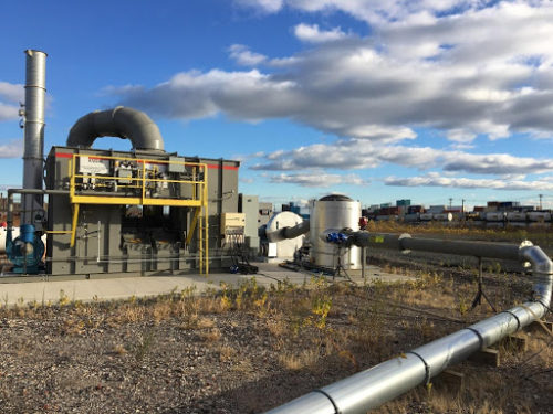
After a thorough evaluation, the design-build consultant selected Anguil to provide the VOC treatment solution. Anguil’s extensive engineering support, industry-leading reliability, and history of solving difficult halogenated destruction problems around the world made them the obvious choice. Anguil engineers recommended a Model 50 Regenerative Thermal Oxidizer (RTO) with an Acid Gas Scrubber. The system is capable of processing up to 5,000 SCFM (8,025 Nm3/hr) of VOC-laden air while providing 99% VOC destruction efficiency and 99% removal by weight of Hydrochloric Acid.
The Result
Anguil’s engineering resources and experience processing halogenated contaminants were crucial to this project. In the Anguil two chamber RTO, polluted air is preheated as it passes over ceramic media beds located in the energy recovery chamber. From there, the process air moves into the combustion chamber where the Volatile Organic Compounds (VOC) are oxidized. Heat from the hot air stream is then recovered by the second ceramic media bed before being exhausted to the acid gas scrubber. A flow diverter poppet valve switches the airflow direction so both energy recovery beds are fully utilized, thereby reducing the auxiliary fuel requirement as much as possible. Anguil’s two chamber RTO is designed to achieve a heat recovery of 95% TER and results in significantly lower operating costs than other thermal oxidation technologies.
 After exiting the RTO, the acid gas laden air is processed through a countercurrent wet scrubber that removes and neutralizes inorganic acids. In the scrubber, a quench system first brings the air temperature down via evaporative cooling by spraying water into the air stream. The cooled air then leaves the quench and enters the bottom of a countercurrent packed tower scrubber. In the tower, a recirculating solution of caustic water is sprayed into the top of the tower and cascades down over the packing material. Any acid gasses remaining in the air stream are absorbed into the water and neutralized by the caustic solution into a salt (brine) solution. To replenish the neutralizing agent, sodium hydroxide solution is added to the recirculating water through pH controls. Similarly, as the brine solution concentrates, ORP/conductivity controls allows saltwater blowdown to leave the system and adds fresh make-up water as necessary.
The specified vapor treatment system included several design features that ensure safe and effective operation in the expected environment. First, an induced draft arrangement was utilized where the process fan is located downstream of the scrubber. An induced draft arrangement is preferred for halogenated applications because it creates a negative air pressure through the entire system where acid gasses are present, minimizing the potential leaking of corrosive gasses which can be forced out of a system under positive pressure. Leakage of s corrosive acid vapors produced by the RTO from the oxidation of halogenated hydrocarbons from equipment connections and penetrations y can corrode the outer shell of the equipment and surrounding environment, as well as posing human health and safety concerns.
Special consideration was given to the materials of construction to ensure performance and reliability in the corrosive environment. Upgraded materials of construction selected for key areas of the RTO are field-proven from Anguil’s many halogenated installations. For example, RTO outer reactor shells were constructed of carbon steel but internally coated with a specialty coating to resist hydrochloric acid corrosion from the inside out. Poppet valves were fabricated from a high nickel alloy, while transitions from the RTO outlet plenum and the acid gas scrubber quench were constructed of hastelloy. The scrubber tower, sump and stack were all fabricated out of FRP (Fiberglass Reinforced Plastic).
Equipment location at the facility was carefully selected to reduce installation costs and minimize equipment downtime. The scrubber was installed inside the treatment building, eliminating the concern of freezing during cold months and costs associated with winterization. The oxidizer was placed outdoors adjacent to the treatment building and near the scrubber system to eliminate extensive ductwork runs.
Anguil’s understanding of the customer’s unique requirements and engineering knowledge of the detailed process conditions resulted in an efficient and reliable system and ultimately another satisfied Anguil customer.