


Keeping Battery Production Profitable and Green
Comments Off on Keeping Battery Production Profitable and GreenBatteries have become a key contributor in the world’s energy transition and critical in the effort to slow climate change. As a result, battery manufacturing technologies and techniques are constantly evolving as producers look to remain competitive, increase storage capacity, and improve efficiency while decreasing battery size and weight. For instance, some producers are turning to a silicone-based anode material to increase battery output and reduce cost; others are exploring mining lithium from seawater to alleviate supply issues. When combined with an unprecedented increase in demand and subsequent production increases, it is fair to say that manufacturers are in a constant state of change. And it is not slowing down: some experts estimate the lithium-ion battery market alone will expand 18% by 2030. In short, we need more energy storage, in smaller batteries, at lower costs.
Lithium-ion batteries are considered the most energy-dense and longest-lasting rechargeable batteries currently available. The process of making them varies, but in general it consists of mixing raw materials followed by a series of coating, laminating, drying, cutting, winding, welding, sealing, forming, pre-charging, and degassing before a final test. However, when battery advancements occur, many of these existing production inputs and manufacturing practices need to change quickly. This can include raw material adjustments, production equipment modifications, or a change in coating techniques, just to name a few. The pollution control technologies employed at the battery manufacturing facilities are also affected by the upstream changes but are often an afterthought by plant personnel.
 Regulated by most state and federal agencies, Volatile Organic Compounds, or VOCs, are pollutants generated in many manufacturing processes. The battery industry is accustomed to these harmful byproducts and the compliance hurdles that accompany them. The organic vapors are dangerous to humans when inhaled in quantities over an extended period. They also interrupt and destroy natural plant processes and play a significant role in the formation of ozone and smog. Hazardous Air Pollutants (HAPs) are a classification of VOCs with additional harmful properties, including potentially causing birth defects, nervous system damage, and even death in concentrated levels; HAPs are also a regulated pollutant from battery manufacturing.
One synthetic graphite anode powder manufacturer was modifying their furnaces to accommodate new products for lithium-ion battery manufacturing. Because their production facility was in a non-attainment area, per the United States Environmental Protection Agency (EPA), air quality standards required them to take special precautions. This meant a Title V permit would be required, as they have the potential to emit more than 100 tons per year (TPY) of VOCs, more than 10 TPY of any single HAP, or more than 25 TPY of any combination of HAPs.
This manufacturing plant in the United States produces high-performance anode material for lithium-ion batteries. A key component of lithium-ion batteries is the anode which stores and releases the lithium ions. Graphite is currently the most commonly used anode material. The process starts with a petroleum coke, which is formed into a synthetic graphite through graphitization. During operation, between 12 to 18 graphite furnaces, which are modular in construction and electrically heated utilizing local hydropower, are needed to meet the production demands.
This facility was no stranger to environmental stewardship. In years prior, they completed an Environmental Assessment to secure financial assistance from the Department of Energy and participate in the American Recovery and Reinvestment Act, which aims to accelerate the development and production of electric-drive vehicles systems to substantially reduce the United States’ consumption of petroleum. In fact, the site itself remains nearly 70% greenspace today.
In keeping with the company’s sustainability goals, they immediately began the search for an effective and efficient air pollution control system. As is the case with many manufacturing operations, process emissions are best destroyed using thermal and catalytic oxidation technologies where time, temperature, and turbulence convert VOCs and HAPs to heat, water vapor, and small amounts of carbon dioxide (CO2).
Widely considered the most energy-efficient oxidation technology, the Regenerative Thermal Oxidizer (RTO) uses these oxidation principles with a unique heat recovery component. Highly effective ceramic media within the oxidizer captures heat from emission combustion and reuses it to preheat incoming pollutants. The RTO also uses uniquely designed poppet valves to divert process air into and out of the oxidizer, properly balance emission loading, maintain destruction efficiency, and optimize heat recovery. Most RTOs are a two-bed design, but they can be designed in a multi-chamber configuration to accommodate larger airflows and achieve destruction efficiencies above 99.7%.
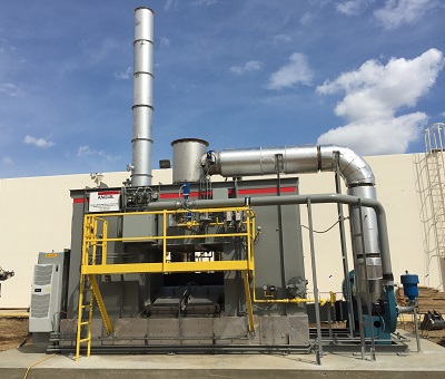
Given the emission loading and low process temperature, the company chose the RTO for its high destruction capability above 99%, and a preowned system was selected to meet their aggressive timeline for compliance. The refurbished, two-bed RTO from Anguil Environmental Systems was delivered, installed, and operational in less than ten weeks. It treats up to 5,000 standard cubic feet per minute (SCFM) of process flow containing methane, ethylene, acetylene, carbon monoxide (CO), benzene, aromatic hydrocarbons, and aliphatic organics from the electrically heated furnaces and corresponding collection hoods. Dilution air at each furnace was added to keep the overall lower explosive limit (LEL) in the duct system below 25%, per code.
 The oxidizer can be operated in a bake-out mode to allow for the removal of organic build-up on the heat exchange media. At a reduced airflow, the outlet temperature is allowed to become elevated before the flow direction is switched, and this hot air vaporizes organic particulate that may have collected. Certain components of the RTO are insulated to prevent the temperature of the outer skin from increasing during bake-out.
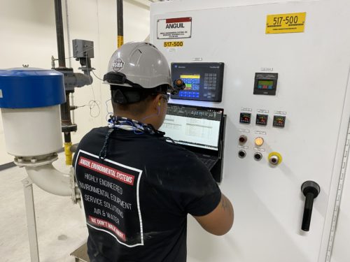
Advanced programmable logic controls record vital oxidizer operating parameters for regulatory reporting and ethernet communications allow for remote diagnostics and service support. A variable frequency drive aids in minimizing operating cost by providing fan turn-down when only low airflow is required in the RTO.
Air pollution and greenhouse gas emissions from this facility remain extremely low due to the efficiency of the pollution control system and utilization of hydropower for the process furnaces. A preowned abatement system was selected to meet an aggressive timeline at this particular facility. However, battery manufacturers all over the world are employing various thermal oxidizer technologies to meet their unique process conditions. For instance, some silicone-based anode precursor manufacturers are utilizing direct-fired oxidizer technologies with downstream particulate control to handle silicon dioxide emissions and remain in compliance. Regardless of the process, oxidizer selection is application specific and should be based on emission constituents, process parameters, efficiency needs and regulatory requirements.
VAM Abatement Project in Shanxi China
Comments Off on VAM Abatement Project in Shanxi China The Challenge
 The Challenge
Ventilation Air Methane (VAM) refers to the ventilating exhaust from coal mines with methane concentrations between 0.1 and 1.9%. Although the concentration is extremely low, the volume of VAM flow is extremely large. Experts predict that more than 50% of all VAM is exhausted from mine ventilation systems directly to atmosphere and remains underutilized; thus the total quantity of methane released is significant. This will damage the ozone (O3) layer in the atmosphere and as a result, contribute to climate change.
The Chinese government is giving an incredible amount of attention to environmental protection and making the corresponding regulations increasingly restrictive. This has hit the coal industry hard. Almost every coal mining enterprise in China must quickly determine how to meet the regulatory standards and at the same time, efficiently utilize the huge amount of VAM.
 The Solution
 The Solution
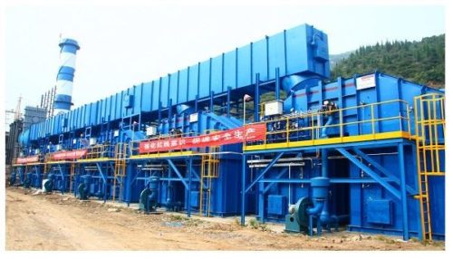
A large coal mining company in Shanxi Province, China, decided to adopt a new technology to capture the VAM and convert it into usable energy. After careful evaluation of the suppliers, Anguil’s team in Shanghai was selected to provide the VAM air pollution control system. Anguil Environmental is headquartered in the United States with more than 1,900 pollution abatement installations around the world. Having a presence in Asia for over two decades, the company has successfully installed hundreds of their pollution abatement systems in China.
The Result
After a comprehensive design review, Anguil recommended the Regenerative Thermal Oxidizer (RTO) technology equipped with hot gas bypass to destroy the VAM emissions and some low concentration Coal Bed Methane (CMM) from the drainage pipes. With Anguil’s RTO design, no auxiliary energy is required for combustion so long as adequate incoming methane concentrations are maintained, typically above 0.35%.
Any excess heat produced during the oxidation process is routed from a hot gas bypass dampers to a boiler system to generate enough steam, which is led to the steam turbine for electricity generation. Different from traditional methods of power generation by burning the coal or gas, using the excess heat from the RTO does not result in the presence of nitrogen oxide (NOX) and can keep the hot air stream at a very stable temperature, which is very important for the following power generation. There is enough steam to also provide building heat during the winter and cooled shaft air during the summer.
This way, the RTO system is not a just destruction technology; the emissions are converted from a greenhouse gas to a revenue generating initiative for the coal mining enterprise as they are able to sell the electricity.
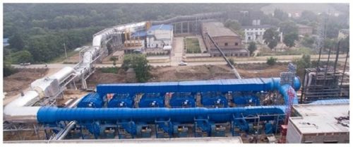
This VAM abatement project consists of six RTOs that process a total exhaust volume of 540,000 Nm3/hr (336,448 SCFM) with an average methane concentration of 1.2%. Once at full capacity, the system will generate electric power with an installed capacity of 15 megawatts which will be returned to the national power grid. Independent reports show that the methane destruction efficiency is above 99.5% and the system is capable of destroying 51 million cubic feet of methane annually.
 Under the close cooperation between the different departments and the full support from Anguil headquarters in the United States, the RTOs were installed on time and within budget. The mining customer recognized Anguil with a Best Engineering Organization Unit Award.
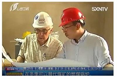
As a new method to utilize a very low concentration of VAM in high efficiency, this project has received extensive attention locally. As reported by several local news outlets, the initiative has been listed as a Methane Zero Net Emission Demonstration Project by China National Development and Reform Commission.
Since the success of this installation, Anguil has received several more orders from other mining companies looking to utilize VAM and reduce their environmental impact. Anguil’s VAM system proves that mining operations can profit by incorporating a properly designed oxidation technology for air purification and combine it with some sort of heat recovery system for steam, heat or electricity production.
Heat Exchanger Replacement Provides Increased Efficiency, Improved Start-up, and Operating Savings
Comments Off on Heat Exchanger Replacement Provides Increased Efficiency, Improved Start-up, and Operating Savings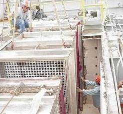
THE CHALLENGE
A manufacturer of insulation films for the electronics industry needed to evaluate their four existing oxidizers. The concern was, due to oxidizer issues, they were not following regulatory requirements. The oxidizers were manufactured by two different companies, one of which was no longer in business. The other was unable to provide an adequate response or solution. An experienced engineering company that would inspect the oxidizers and provide quality repairs for any problems that were discovered was necessary.
After evaluating the service capabilities of several equipment manufacturers and engineering consultants, they chose Anguil Environmental Systems because of their full-service solutions.
Anguil’s rigorous 75-point preventive maintenance evaluation (PME) discovered minor problems with three of the units and a major problem with the largest oxidizer, a 13,500 SCFM (21667.5 Nm³/hr) catalytic oxidizer. Anguil’s recommendations for the three smaller oxidizers greatly improved their safety and performance. Many of the suggestions from Anguil were easily implemented by the plant’s in-house maintenance staff. However, the largest oxidizer required more intensive application engineering and a comprehensive air pollution control solution.
THE SOLUTION
The larger 13,500 SCFM (21667.5 Nm³/hr) system had both a primary and secondary heat exchanger. The primary heat exchanger recovers energy from the combustion chamber exhaust and transfers it to the incoming process air stream to reduce fuel consumption. The secondary heat exchanger recovers additional energy from the primary heat exchanger outlet flow and uses this energy to preheat the air source used in the process. In this case, the secondary heat exchanger is integral to the plant’s coating process; it is used to heat the tower dryer of the AISCO coating machine. The plant engineers noticed a steady decline in the heat available from the oxidizer and secondary heat exchanger. By the time Anguil was invited in for their PME, the oxidizer took up to six hours to sufficiently heat the coater before production could begin. During the six hours of warm-up, the oxidizer had to be supplied with extra natural gas. This fuel consumption led to an operating cost of approximately $266 per startup.
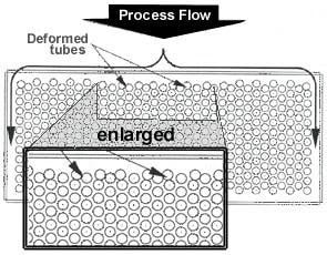 Anguil’s inspection further revealed significant damage to the heat exchanger. A third of the front tubes had separated from the bottom plenum, deforming into the second row of tubes. This effectively blocked around 25% of flow through the remainder of the exchanger. Anguil also pinpointed several areas where the airflow was bypassing the exchanger, traveling in the gaps between the exchanger and the ceramic insulation and passing through tears in the tubesheet and top plenum. The combination of bypass areas and the tubesheet tears allowed solvent vapors to circumvent the combustion chamber, greatly lowering the destruction efficiency of the oxidizer.
Anguil performed a destruction efficiency test on the oxidizer when the coated web used 100% toluene as a solvent. Under normal conditions, an oxidizer of this type should have little difficulty in attaining 98% destruction efficiency or better. Due to the airflow bypassing the combustion chamber, the oxidizer was achieving only 93.6% destruction efficiency. Not meeting the regulatory emission requirements.
Replacing the oxidizer would have radically interrupted the customer’s manufacturing schedule, resulting in capital cost increases that were unacceptable. Anguil’s solution eliminated any production disruptions by performing repairs and design enhancements over several scheduled downtimes.
THE RESULT
The first step was to replace both the primary and secondary heat exchangers. The onsite work was performed over a three-day weekend when the customer already had a planned plant shutdown.
The replacement heat exchangers significantly improved the performance of the 13,500 SCFM (21667.5 Nm³/hr) oxidizer. Previously, the oxidizer had to be run for up to six hours to meet the necessary temperature at a fuel cost estimate of $266/per startup. After the replacement, the required process air temperature is achieved in one hour. The improved efficiency results in operating cost savings of approximately $230 per startup and up to $30,000 annually. The impact of the retrofitted heat exchangers went beyond fuel savings; the improved start-up time has reduced plant downtime and increased production. They have also improved the destruction efficiency of the oxidation system and put the company in compliance.
Anguil’s analysis detailed other cost saving suggestions for the company, including:
- Ductwork adjustments for more efficient oxidizer operation
- Heat exchanger maintenance suggestions for all four oxidizers
- Review of safety controls and upgrade recommendations
- Variable Frequency Drive for the fan on the largest oxidizer to accommodate airflow changes more efficiently
- Burner maintenance suggestions
Anguil also performed airflow analysis of all processes. This information will help the company plan and budget for future growth.
The retrofitted system is currently exceeding the regulatory requirements and providing an efficient heat source for the coating lines. The Anguil service team’s expert troubleshooting and quality turnkey solution capabilities have led to another satisfied customer.
Waste Heat Generates Steam and Savings
Comments Off on Waste Heat Generates Steam and Savings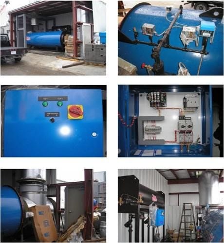
THE CHALLENGE
A coil coating facility purchased a new 15,000 SCFM (24,075 Nm³/hr) regenerative thermal oxidizer (RTO), which had a nominal heat transfer efficiency rate of 90% thermal energy recovery (TER). The RTO unit was designed with supplemental fuel injection (SFI), which is used during low volatile organic compound (VOC) loading conditions to help save fuel costs. While the SFI was an improvement, the owner was looking for additional ways to decrease their exhaust air temperature and reduce operating costs.
THE SOLUTION
The high exhaust temperature (above 650°F, 343.34°C) and large airflow (12,650 SCFM, 20,303 Nm³/hr) in the oxidizer exhaust stack provided an opportunity to add energy recovery measures. Because the process required a significant amount of steam, it would likely provide the quickest results for an energy recovery project.
THE RESULT
Anguil Environmental installed a skid-mounted air-to-steam waste heat recovery boiler to recover exhaust waste heat from the natural gas fired thermal oxidizer and produce 25 psig of steam. The boilers use X-ID tubing for enhanced heat transfer through the helical ribs on the inside of the tubes.
The waste heat boiler package included forced circulation, fire tube, and heat recovery steam generator. The unit has automatic, modulating, exhaust gas bypass that is controlled by steam pressure. A boiler feedwater and blowdown separator were included as part of the package.
Installing the waste heat boiler system recovered approximately 2.58 MM BTU/hr of energy, lowering the stack temperature to 338°F (170°C). The addition of the waste heat boiler on this application saved the facility $216,770 per year. The total return period for this project was less than six months, demonstrating how targeted waste heat recovery can boost efficiency, and deliver a return on investment.
Oxidizer Energy Recovery Options
Comments Off on Oxidizer Energy Recovery Options The Challenge
 The Challenge
The mainstream media today is full of allusions to energy awareness and conservation. Just as visible these days are media references to astronomical dollar figures that can boggle the mind. This article does not seek to break out of that mold, but rather to conform to it, as Oxidizer Stack Heat Recovery offers a tremendous opportunity for both energy conservation and energy cost reduction.
The Solution
Consider the following: at any hour of the day there are likely to be more than 10,000 oxidizer systems in service, using a high temperature reaction chamber (with or without catalyst) to treat the exhaust gases from a wide range of industrial processes. The final component of nearly all of these oxidizer systems is an exhaust stack, where the treated exhaust gases are released to the atmosphere at elevated temperatures.
Historically, oxidizer systems have been sized to treat exhaust air flows from 100 SCFM (Standard Cubic Feet per Minute) (160.5 Nm3/hr) up to several hundred thousand SCFM. But conservatively, the average oxidizer system airflow processing capability (i.e. “size”) can be estimated to be between 15,000 and 20,000 SCFM (24,075-32,100 Nm3/hr).
Now, considering these 10,000 stacks emitting hot, treated gases to the atmosphere around the clock; if heat recovery equipment capable of dropping the exhaust stack temperature by 100 ˚F could be installed into each one of them, this would lead to an overall value of over 18 billion BTUs (British Thermal Unit) per hour of energy conservation!
Assuming $10/MM BTU and year round operation – this equates to recovering over $1.5 billion (US Dollars) worth of energy per year!
Taking this into account, it is no surprise that a wide range of stack energy recovery options have been developed and marketed to end-users of oxidizer systems. This article will discuss three important aspects of energy reclamation from hot oxidizer stacks:
- Energy reclamation from oxidizer stacks is one of three potential areas of optimization for oxidizer systems.
- There are distinct challenges that must be addressed in the process of evaluating potential energy savings options.
- There are multiple potential equipment options for this application, each with its own benefits and limitations.
 The Result
 The Result
The ABC’s of Oxidizer Stack Energy Recovery
Oxidizer Energy Recovery Options
Using ABC’s in the title of this section is actually a misnomer. Truthfully, the letters A and B should be set aside and the caption should read – The CDE’s of Oxidizer Stack Energy Recovery. The reason for this is twofold:
First of all, any plan for recovering waste heat in the exhaust stack of an oxidizer system is already a Plan C. For anyone taking a hard look at optimizing the energy efficiency of an oxidizer system as a whole, Plan A should consider ‘upstream’ opportunities. For example, retrofits that reduce overall airflow to the oxidizer system and/or increase the concentration of solvents to be treated. Plan B should focus on the internal TER (Thermal Energy Recovery) of the oxidizer system itself. After airflow reduction, maximizing the internal energy recovery of an oxidizer system will almost always lead to the best project payback.
Hence, it follows that energy recovery in the exhaust stack of the oxidizer is Plan C. Now calling it Plan C is by no means meant to downplay the opportunities associated with oxidizer stack energy recovery. The only intent is to fit the concept into the greater framework of energy usage in the oxidizer system as a whole. There are many reasons why Plan A and/or Plan B as defined above may not be attractive or even feasible, making Plan C: Energy Recovery in the Oxidizer Exhaust Stack, the best overall choice for energy conservation efforts.
The second reason that the letters C, D and E are a better fit for the title of this section is that those three letters represent the challenges associated with energy recovery efforts in oxidizer exhaust stacks, namely:
- CAPTURING the energy from the stack itself
- DELIVERING the energy back into the plant cost-effectively
- EMPLOYING the recovered energy effectively inside the plant
Following is a brief discussion of each of these challenges along with the different options for recovering oxidizer stack heat.
Challenge #1: Capturing the Energy
Of the three challenges, the first – Capturing the Energy – is usually the easiest to evaluate and estimate. By simply knowing the airflow and temperature of the exhaust gases in the oxidizer stack, suppliers of energy recovery equipment can quickly begin to model an appropriate device for reclaiming energy effectively. It is often during this first challenge that the overall opportunity for yearly savings is also quantified.
The more information that an oxidizer end-user can provide at this juncture, the more realistic the opportunity analysis can be. At a minimum, those considering stack energy recovery should gather the following before beginning this process:
- Expected airflow and average temperature in the oxidizer stack
- Expected hours of operation per year
- Current energy rates for the plant (gas or oil and electric)
The first two items are often monitored already on a continuous basis in oxidizer data recorders. If that is not the case for a particular system, the most recent EPA (Environmental Protection Agency) stack testing data can be an excellent source for this information.
Two other issues for consideration during this phase of an evaluation are:
Constituents in the exhaust gases (and especially their dew points): Any effort to reclaim energy in the exhaust stack of an oxidizer will lower the oxidizer exhaust gas temperature, bringing with it the potential for condensation of acids. Suppliers of energy recovery equipment will typically take care to ensure that final stack temperature is above any acid dew points. Given the typical solvent laden exhaust from printing presses, this is rarely an issue of concern for oxidizer systems in the flexographic printing industry.
Adding energy recovery equipment to an oxidizer exhaust stack will also come with a system back-pressure penalty. The existing oxidizer fan will usually be tasked with pushing or pulling air through the ‘hot side’ of the added heat recovery component. To keep overall project payback attractive, the goal is usually to choose energy recovery equipment that will limit the added system back-pressure to an amount that the existing oxidizer system fan can handle without major modification. Therefore, knowing the additional capacity available in the oxidizer system fan will help narrow down which cost-effective options for energy recovery are feasible.
Challenge #1 for a typical application may look like this:
Consider a flexographic printer with a ten year old 20,000 SCFM (32,100 Nm3/hr) Regenerative Thermal Oxidizer (RTO). The combined exhaust from all dryers and capture hoods routed to the RTO is 20,000 SCFM (32,100 Nm3/hr) at approximately 150˚F (65.5˚C). The average exhaust temperature from the RTO is 275˚F (135˚C).
Plan C – A 50% effective heat exchanger installed in the oxidizer exhaust stack to transfer the waste heat to air or fluid would drop the stack temperature by approximately 125˚F (51.7˚C) – capturing approximately 2.7 MM BTU/hr. If this energy was 100% useful inside the plant and the plant operated around the clock, this could lead to a yearly savings of up to $225,000.00. A payback of one to two years is certainly possible for a project of this nature.
By comparison:
Plan A – reducing airflow to the RTO by 10% could save approximately 0.3 MM BTU/hr or up to $25,200.00/year. This could likely be accomplished with very little capital investment at all. A payback of less than six months is possible for this option.
Plan B – for the data presented, this RTO is operating with an internal thermal energy recovery (TER) of approximately 92%. Installing additional ceramic heat recovery media to raise the TER to 95% could save approximately 1.0 MM BTU/hr or up to $84,000.00/year. A payback of less than one year is possible for this option.
Challenge #2: Delivering the Energy Back into the Plant Facility Cost Effectively
As seen in Challenge #1, sizing energy recovery equipment and estimating the overall savings opportunity with oxidizer stack energy recovery are not difficult tasks. To take an opportunity analysis and turn it into an actual payback period however, one has to determine the cost of installing the equipment and providing the infrastructure for delivering captured energy back to the plant.
For a cursory analysis, some will take the cost of the energy recovery equipment and double it, calling that the estimated cost of installation. (i.e. Total Estimated Cost = One Part Equipment Cost + Two Parts Installation Cost) This can provide for a quick check of whether a particular idea merits additional investigation. To obtain true payback numbers then a site visit by different tradespeople to estimate the overall cost of energy recovery system installation will be necessary. Fans and/or pumps, control valves, thermocouples, etc. will all need to be both mechanically installed and electrically wired to an existing or new control system. This is often the challenge where the overall project feasibility hangs in the balance.
Challenge #3: Employing the Recovered Energy Effectively inside the Plant Facility
The final challenge is also extremely important for optimizing energy recovery project payback. Ideally, the oxidizer end-user should look for ways in which recovered stack energy can be used in the same process that the oxidizer is connected to. This typically provides the best payback because there are energy demands by that process at nearly all times that oxidizer waste heat is available. In contrast, projects focused on recovering oxidizer exhaust stack energy to help heat a facility, for example, may only be useful for part of the year.
Oxidizer Stack Energy Recovery Options
Oxidizer stack heat has been recovered to perform a wide variety of functions in the plant environment.
Air-to-air heat exchangers have been used to provide pre-warmed fresh air back to process ovens, dryers and/or plant make up air units.
Air-to-fluid heat exchangers have been used to transfer oxidizer stack heat to boiler feed water, plant makeup water, process water, glycol and other thermal fluid loops.
In extreme cases, waste heat boilers have been used with oxidizer stack heat to create steam.
And on the horizon, heat-to-power systems are in development for reclaiming oxidizer stack heat and creating electricity.
One additional option that has been used sparingly is taking hot oxidizer stack air directly back for use in production processes. This is sometimes referred to as Direct Heat Recovery, while the options mentioned above would be termed Indirect Heat Recovery. Direct Heat Recovery from oxidizer stacks is generally shied away from due to the risks of introducing products of incomplete combustion back into a plant environment or the risk of oxidizer “oven dirt” contaminating product, but there are limited cases where this form of oxidizer stack energy recovery has been used effectively.
Each of these options for recovering heat from oxidizer exhaust stacks can be considered within the framework of the three challenges discussed previously.
Air-to-Air Heat Recovery
Probably the most common energy recovery product applied to oxidizer stacks is an air-to-air heat exchanger. Be it a shell-and-tube or plate type heat exchanger, there is a cold side air stream (typically fresh air) and a hot side air stream (typically the oxidizer exhaust) that are used for heat transfer.
Air-to-air heat exchangers have been integral to oxidizers themselves for decades so it is a well-known technology for oxidizer manufacturers to incorporate into an overall system. The programs for sizing air-to-air heat exchangers are quick and easy to use. There are a wide variety of footprints and physical layouts for ease of installation. There are also many low back pressure models that work well with existing oxidizer system fans.
The limiting factor for air-to-air heat recovery in oxidizer exhaust stacks is Challenge #2: Delivering the Energy Back into the Plant Facility Cost Effectively. With air-to-air heat recovery, insulated ductwork is required to transport captured heat back into the facility. Costs for running ductwork in a plant vary widely and can also add up very quickly. The best applications are those with short duct runs for returning heated air.
Air-to-Fluid Heat Recovery
Air-to-fluid heat exchangers are the second most common energy recovery product for oxidizer stacks. As the name implies, heat is transferred from the hot oxidizer exhaust air (again the hot side air stream) to a circulating fluid (the cold side stream). This is typically accomplished by passing the hot air over a coil containing the fluid to be heated. As with air-to-air heat recovery there are a variety of low back pressure designs that can allow installation into an oxidizer exhaust stack without adversely affecting the oxidizer system.
Because piping is less expensive than ducting, air-to-fluid heat recovery has a definite advantage over air-to-air heat recovery when considering Challenge #2: Delivering the Energy Back into the Plant Facility Cost Effectively. However, unless the heated fluid is used directly back in the process that the oxidizer is connected to, Challenge #3: Employing the Recovered Energy Effectively inside the Plant Facility, can be more difficult to address with air-to-fluid heat recovery. Meeting this challenge requires a detailed analysis of the demands for energy in the fluid system versus the availability of waste heat in the oxidizer stack. For example, in some plants the biggest hot water demands come in shutdown situations when the oxidizer is not running.
Air-to-Steam Heat Recovery (Waste Heat Recovery Boilers)
When the solvent laden air sent to an oxidizer system is sufficiently rich, the oxidizer’s internal heat recovery component may need to be partially bypassed or forgone completely. This leads to higher than normal oxidizer stack temperatures and allows for additional options in heat recovery equipment. One such option is a waste heat recovery boiler to recover oxidizer exhaust stack heat and produce steam. Waste heat recovery boilers are custom sized for a particular exhaust gas capacity as well as required steam pressure. A variety of systems are available in vertical, horizontal, single or multi pass configurations. Oxidizers on most applications rarely have the necessary solvent loading and corresponding exhaust stack temperatures to sustain this option.
Heat-to-Power
Sometimes referred to as cogeneration, heat-to-power is an emerging technology that is capable of sending kilowatts directly back into a facility for electrical power. The concept has been implemented on different applications throughout the world but is only now being integrated with combustion devices such as oxidizers. Heat-to-power systems can currently generate up to 100kw per hour from a modest heat source. However, the payback is normally greater than three years, the value most companies use for acceptable capital investment. As electricity costs increase and greater efficiencies are achieved with the technology it will be a very attractive option in the near future. Today, heat-to-power is not necessarily a cost reduction strategy but rather a green initiative that could be used to promote a company as a leader in energy conservation.
Oxidizer stacks represent a significant opportunity for the reclamation of energy. This applies to all oxidizer systems – including both the aging catalytic oxidizers popular in the industry years ago as well as the newer, high efficiency regenerative thermal oxidizers (RTOs) being supplied today. Achieving a cost-effective installation of energy recovery equipment with an attractive payback is not without challenges, but those challenges are being met today in a variety of ways.
Air-to-Water Heat Exchanger Reduces Operating Costs by $120,000 per year
Comments Off on Air-to-Water Heat Exchanger Reduces Operating Costs by $120,000 per year
THE CHALLENGE
When designing an oxidizer, local and federal requirements are taken seriously into consideration. Each system is customized for the location it will be run at. Sometimes, a unit must be moved to a different location. It may have been purchased by a different company, or the owner may be moving to a new location. No matter the reason for the move, the system will need to be reassessed and modified to ensure compliance with regulations at the new location.
When a leading pharmaceutical manufacturer needed to relocate an oxidizer across the United States, they turned to the expertise of Anguil Environmental Systems. The company’s 5,000 SCFM (8,025 Nm³/hr) oxidizer needed to be evaluated and updated to achieve the performance expectations at the new facility, which were different from the regulations at the original location.
THE SOLUTION
Anguil began by conducting a detailed review of the system. A field service engineer went on site to inspect the oxidizer. A report detailing the condition of the oxidizer at its current location was generated, as well as a written procedure for the proper disassembly and reassembly of the equipment. The service engineer made recommendations outlining the modifications necessary to make the unit run at the new facility’s required energy, and destruction efficiency rate.
THE RESULT
With the review complete, Anguil worked closely with the customer to update the system. The modifications included a control package upgrade and a new hot gas bypass damper. To address the energy recovery requirements at the new facility, an economizer was installed between the oxidizer and exhaust stack to transfer heat to water. The exhaust heat from the stack was transferred to the Anguil economizer which created hot water. This otherwise lost energy was captured and used in various applications such as boiler feedwater, cold makeup water, processed water, glycol, and thermal fluids.
The stainless-steel system tube and fin style heat exchanger has access doors for inspecting and cleaning the tubes. The exhaust flow from the catalytic oxidizer is 5,400 SCFM (8,667 Nm³/hr) and the temperature is 450°F (232°C). Roughly 160 GPM of water is heated to 140°F (60°C) with the economizer. The total energy recovered was 1.43 MM BTU/hr or an estimated total savings of $120,512 per year. The upgrades not only optimized performance but also delivered substantial energy savings to help the customer meet both their operational and sustainability goals.