


Solutions for Coating VOC & HAP Abatement
Comments Off on Solutions for Coating VOC & HAP AbatementThe Challenge
Our planet is getting warmer. At what rate it is occurring or how much human activity has to do with the increasing temperatures is a heated debate. One thing we do know for sure is that Carbon Dioxide (CO2) is a contributing factor in global warming and humans are responsible for a large portion of these emissions. These days, many individuals and businesses alike are trying to reduce their environmental impact and GHG (Green House Gas) emissions. What the average person does not realize is that they have two types of footprints, a primary and secondary. The primary footprint is a measure of our direct emissions of CO2 from the burning of fossil fuels including domestic energy consumption and transportation, e.g. car and plane. The secondary footprint is a measure of indirect CO2 emissions from the whole lifecycle of products we use, those associated with their manufacturing and eventual breakdown. To put it simply: the more we buy, the more emissions will be caused on our behalf.
The Solution
Thankfully companies like Corus, a subsidiary of Tata Steel, are doing their part to reduce the world’s secondary footprint by improving the energy efficiency of their manufacturing processes. Corus is Europe’s second largest steel producer and comprises three operating divisions: Strip Products, Long Products, and Distribution and Building Systems. Corus Colors as part of the Strip Products Division is an international business manufacturing pre-finished steel for the building envelope, domestic appliances and manufactured goods markets.
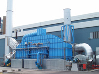 Corus Colors Shotton Works, located at Deeside, North Wales, produces organic paint coated prefinished steel principally for cladding, composite walling and roofing applications within the building and construction sector both in the UK and overseas. There are two manufacturing processes at Shotton Works for coating steel strips with paint. They use a series of driven roller coaters and industrial curing ovens, controlled within a continuous process line, that are capable of applying protective and decorative high quality finishes to the galvanized flat steel strip substrate. The No1 Colorcoat Line process is capable of coating strip widths up to 1400mm with a thickness up to 1.6mm, giving a weekly throughput capability of up to 4000 tonnes subject to product type and dimensions.
This manufacturing process requires large amounts of natural gas to ensure proper application and fast curing time in the ovens, which, in turn generates a substantial amount of CO2 and NOX (Nitrous Oxides). In addition to these emissions, the solvent-based coatings release HAPs (Hazardous Air Pollutants) and VOCs (Volatile Organic Compounds) during the drying process that need to be treated by an air pollution control device such as an oxidiser. New oxidiser systems are capable of destroying over 99% of the HAPs and VOCs through the process of high temperature destruction with very little fuel consumption. However older technologies can be a source of CO2 and NOX as well as the requirement for high maintenance and large operating expenditures.
The Result
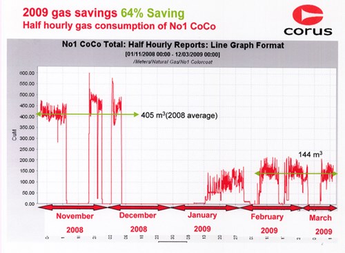 Pollution control initiatives are nothing new to Corus, the company has been monitoring and controlling their oven emissions at the Shotton Works, North Wales facility, since the 1970’s. Their first oxidiser/incinerator was installed on the paint coating processes for abating exhaust gases and solvents. Even then, the company was thinking green by utilizing waste heat from these older oxidisers/incinerators to preheat the ovens and to supply their manufacturing facility with additional process steam. However, as environmental regulations tightened, energy prices increased and new technologies emerged, the company decided to re-evaluate their entire system as part of their manufacturing efficiency improvements as well as the wider Corporate Responsibility Program for energy usage reduction. The objective was to reduce the gas consumption by at least 45% and increase processing speeds on certain products but they quickly realised another benefit to their sustainable energy plans…a much smaller carbon footprint.
Looking for a sustainable energy solution, they turned to Spooner Industries in the United Kingdom who have worked closely with Corus on a number of projects over the past 30 years. Oven technology and safety regulations had changed dramatically since the line was first installed, but Spooner was able to successfully complete several upgrades that brought the system up to current standards and increased its flexibility.
- Each zone was retrofitted with a special low NOX burner to reduce emissions.
- Variable frequency drives or inverters on every oven fan were incorporated into the control system to make each section more efficient and reduce electrical consumption.
- The ductwork was changed to bring hot air into the system quickly, reducing maintenance issues.
- New thermocouples (temperature measurement), pressure transmitters, pressure switches and flow measurement systems were installed in the ovens to bring the equipment up to today’s technology standards, allowing for remote monitoring and fine-tuning.
- A new computer controlled system was integrated with the SCADA (System Control and Data Acquisition) program. The proper PLC (Programmable Logic Controller) allows the central Corus system to communicate with the ovens so they can be set up for different production runs, eliminating errors and decreasing setup time.
The oven alterations brought this production line from the least efficient in the Corus group to the most, meeting one of the two objectives for the company. While some of these improvements reduced the company’s environmental footprint and gas consumption, the increased throughput would further complicate their environmental responsibilities. Two existing, inefficient oxidisers for the Prime and Finish Ovens were being used to control VOC and HAP emissions at the North Wales facility. To achieve proper destruction the systems required large amounts of natural gas which affected operating expenses and contributed to CO2 and NOX emissions. Furthermore, breakdowns and maintenance problems were not only costing the company money to repair but also revenue in lost production. Because the oven and oxidiser are so vital to each other, Corus wanted a solution provider with experience and knowledge on both. In addition, they were looking for a system with low operating costs and heat recovery capabilities that could achieve 99.5% DRE (Destruction Removal Efficiency) which was well above their permit requirements.
Spooner, having recently partnered with Anguil Environmental Systems in The United States to fabricate and install their oxidiser designs on applications throughout Europe, was confident that it could be done. After consulting with the engineers at both Spooner Industries and Anguil Environmental Systems, Corus made the decision to replace their multiple air pollution control systems with one, RTO (Regenerative Thermal Oxidiser) from Spooner Anguil. It would give them the desired efficiency and single-source solution they were looking for. The system has the following features and benefits:
- The oxidiser is a 3-chamber design that processes 83,000 Nm3/hr (55,000 SCFM) of air, achieving 99%+ DRE without visible emissions and 85%+ heat recovery for energy-efficient operation.
- The RTO self-sustains at low solvent-loading conditions, meaning that once the oxidiser is at operating temperature and receiving process airflow it requires no additional fuel for emission destruction, releasing very little CO2 and NOX.
- A secondary heat exchanger sends waste heat directly back to the ovens, reducing the amount of natural gas required for product curing.
- Stainless-steel components throughout the system prevent corrosion and allow for high temperature process streams.
- A hot-gas bypass on the RTO is used during high loading situations to avoid overheating the oxidiser.
- An intelligent bake-out feature cleans the RTO of condensable organics without internal fires or safety concerns.
- The control panel has a large operator screen with a built-in maintenance manual and troubleshooting guide which makes for ease of use.
- Corus has made a significant investment for the new equipment, upgrades and implementation of this energy reduction project. It has dropped their cost, per ton of steel produced, considerably and they estimate the payback will be less than one year.
The reduction in carbon emissions and energy consumption from this facility is dramatic. Their gas usage has dropped by more than 60%, an average reduction of 522 m³/hr (or 5742 kW) per hour – saving over £1million a year. At 181 grams of CO2 produced per KWH used, Corus is preventing 1 tonne of carbon from reaching our atmosphere each hour, nearly 8,000 tonnes per year.
With innovation and continuous improvement at the heart of its business, the company is already planning for similar modifications at other Corus plants. A spokesperson from Corus commented: “We are committed to minimizing the environmental impact of our operations and our products through the adoption of sustainable practices and continuous improvement in environmental performance.”
Frac Water Reuse Technologies
Comments Off on Frac Water Reuse TechnologiesThe Challenge
The worldwide energy sector has accelerated the development of its unconventional oil and gas resources through increased use of horizontal drilling and hydraulic fracturing practices. Water is an essential element in the fracturing process and the recycling or reuse of spent water can dramatically reduce costs. The volume of water required to fracture a well varies, but it generally ranges from one million gallons to five million gallons. Operators face difficult challenges securing water sources for their operations, especially already dry regions. Furthermore, the management of waste water associated with hydraulic fracturing has an environmental impact and associated cost.
The development of technology to recycle and reuse this water is now becoming critical and Anguil has integrated solutions to help. We have developed an effective water recycling system that allows well operators to safely reuse water without jeopardizing well output.
The Solution
WATER RECYCLE AND REUSE
Water generated during drilling, well completion, and production is categorized either as flowback or produced water. Flowback water is the initial fluid produced after hydraulic fracturing and is typically recovered during the first six weeks of well production. The flowback water characteristics stem from the initial source water, the natural formation brine, fracturing fluid additives, proppants, and drilling fluids. Generally, 20-40% of the fracturing fluid volume is recovered as flowback. Produced water is the water which naturally exists within shale formation and is recovered concurrently with oil and gas. After the initial flowback period, produced water resembles the characteristics of the formation brine. The volume recovery rate of produced water is lower in comparison to the flowback, but occurs over the decades of a well’s lifetime. Currently, the majority of flowback and produced water is disposed of in salt water disposal wells.
Recycling and reuse of flowback and/or produced water reduces fresh water demand and the associated costs of water purchase, transportation, and disposal. In contrast to the usual practice of complete disposal, a portion of the flowback is treated for reuse either onsite or at an adjacent well. The primary economic benefit from recycling is a significant reduction in the number of truck loads required to ship fresh water to the well site and the flowback water offsite. Environmental benefits include reduced reliance on and competition for fresh water sources, a reduced carbon footprint from trucking, and less stress on the local infrastructure.
Treatment requirements for flowback and produced water are normally established by the company performing the well completion. Knowledge of the fracture fluid employed is required when considering the recycling methodology in order to identify the required treatment characteristics. Two common fracturing fluids are slick water and gels. Slickwater is normally used for natural gas production, whereas gels are often deployed for oil field development.
ANGUIL’S FRAC WATER REUSE SYSTEM
Since there is a wide variation in flowback and produced water quality in oil and gas fields, Anguil Aqua Systems is presently focused on the treatment of flowback and/or produced water from natural gas wells.
Previously, the high levels of Total Dissolved Solids (TDS) in produced water were thought to render it unusable. However, well service companies have demonstrated that moderate TDS levels in recycled water do not impact well production capacity. Hence our solution is to focus on the minimization of Total Suspended Solids (TSS) and, overall reduction of bacteria and other contaminants affecting the fracturing fluid additives.
Of the many approaches to the minimization of TSS, the Anguil solution is a ballasted flocculation system. Similar systems have been successfully employed to treat drinking water as well as municipal and industrial waste waters containing many of the same contaminants found in flowback and produced waters.
SYSTEM DESCRIPTION
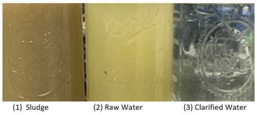
The diagram below depicts the flow pattern for the clarification process. In the first tank, the raw water or influent is combined with a coagulant, commonly ferrous sulfate, ferric sulfate, ferric chloride, or alum. The coagulated influent then passes into the flocculation tank where a polymer and a ballast material such as microsand, iron oxides, or chemically enhanced sludge is added. Coagulation and sedimentation times are reduced by the addition of chemical additives and the ballast material. After ballast and polymer additions, the flocculated water then proceeds to the third tank where additional mixing occurs, allowing the floc to coalesce into larger precipitates. The matured, flocculated water proceeds to the clarification tank where the floc is separated from the water by passing through plate or tube settlers. Clarified water then exits from the top of the system.
Settled floc and ballast material are collected and pumped to the ballast recovery unit where the ballast is separated from the waste solids. The waste solids are sent to disposal and the recovered ballast is returned to the first flocculation tank. We can provide treatment systems which help improve injection facilities operations and maintenance, reducing injection pressures and minimizing acid jobs by keeping your wells from fouling. Furthermore, our solutions include treatment options to enhance your oil recovery and treat for hydrogen sulfide control.
The Result
As a member of the Gas Processors Suppliers Association, Anguil is heavily invested in industry’s success and future. Countless air pollution control installations at natural gas processing and petroleum refining sites gives us the necessary knowledge to address your water treatment needs safely, effectively and within your demanding production schedules.
- Reuse of Flowback and Produced Water: Physical and chemical treatment system that reduces suspended solids to acceptable reuse standards for hydraulic fracturing.
- Mobile Precipitation: A system easily deployed on site, allowing treatment for multi-well completions, or transport to a nearby well.
- High Contaminant Removal: Total Suspended Solids (TSS), turbidity, oil/grease, color, and bacteria.
- Chemical Coagulation: A wide range of available coagulants and polymers allows customization to site specific needs.
- Automated Chemical Feed System: Treatment begins with proper dosing of chemicals to precipitate dissolved contaminants. The Frac Water Reuse System incorporates chemical metering pumps, day tanks and pH instrumentation to ensure treatment objectives are being achieved.
- Lower Costs: Ballasted clarification allows for smaller equipment footprint, reduced power consumption, and reasonable chemical use. Recovery and reuse of ballast material lowers consumable costs.
- Short Term Lease Agreements: Flexibility to only pay for water recycling system during peak water demand.
- Customized Service and Project Management Contracts: Anguil personnel can be contracted to provide continuous service and/or operation of the entire water recycling system.
Wastewater Compliance Techniques For Food Processors
Comments Off on Wastewater Compliance Techniques For Food ProcessorsThe Challenge
Food production has always been a demanding and competitive process. Executives are constantly challenged by slow product development cycles, competition from healthier alternatives and even food fraud. In today’s climate, producers now worry they can be perceived as environmentally and socially irresponsible, resulting in some retail chains refusing to stock their brands until they make often intensive and expensive changes.
Many producers are being hit by a second blow to their profit margins due to failing and overcapacity Publicly Operated Treatment Works (POTWs). Wastewater previously discharged with little care may now be subject to volume and contaminant surcharges as POTWs repair infrastructure and struggle to meet increased EPA discharge regulations.
Finally, treatment system operators with decades of experience are retiring and their tribal knowledge of how to run their antiquated treatment system retires with them. This leaves owners and executives wondering how to replace that knowledge base and ensure they remain in compliance.
In the face of increased regulatory control and rising environmental concerns about wastewater, food producers are looking for cost-effective ways to stay in compliance while keeping operating costs low. Anguil’s four-step approach to industrial wastewater treatment challenges can help producers address economical, operational and compliance challenges.
The Solution
NAILING DOWN THE REQUIREMENTS
Anguil Environmental provides highly engineered environmental equipment and service solutions that solve complex industrial air and water challenges. When we are aiding companies with water projects, we follow a very simple but effective process to deliver systems tailored to each customer’s specific needs.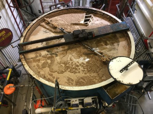
The first step is to understand the business case.
We collaborate with the client to understand their challenges, and determine the project needs and objectives. We gather benchmark data to assist with alignment of solutions that offer the best return on investment (ROI), then work with the customer to understand their decision process and criteria to ensure we can check all their boxes. For example, is our customer willing to spend more on controls and automation to minimize operator involvement or to better deploy staff in other areas of the facility?
In this case, a client was looking at TSS surcharge costs of $40,000 per quarter and a surcharge of $20,000 per quarter for acidic discharge waters. The client was essentially looking at $240,000 in increased operating costs per year. BOD did not receive a surcharge, and overall water volume costs were negligible.
The second step is to explore and validate all treatment and operational processes in the Anguil lab.
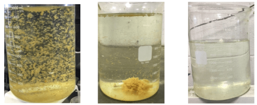
Anguil validates all potential treatment and process options that align with the customer objectives. A client wanted to determine a solution for TSS removal below discharge requirements. We started by asking the client to send a wastewater sample to our inhouse wet lab to validate potential treatment protocols. We determined pH / polymer protocol resulted in TSS removals well below the discharge requirements. Hence, we determined a simple scheme could meet the customer’s goals.
After bench-testing provided us with a viable treatment option, we generated a simple Process Flow Diagram (PFD) to illustrate the primary equipment integrated into the treatment train. This train included the appropriate equalization and buffer tanks, pump logistics, clarifier, and a filter press for solids handling. In our discussion with the client, we offered additional options including:
- Ballasted flocculation versus straight clarification to lessen the overall footprint
- A rotary vacuum drum for dewatering instead of a filter press to lessen the burden on facility personnel and lower the liquid content (weight) of solids being shipped off site
Even though the customer appreciated the pros of each option, after reviewing the capital cost increase, the client decided to remain with the original approach.
The third step is a pilot system onsite to test waters in-situ:
With the client satisfied with our lab trials, we asked if they required a pilot system to validate the treatment approach insitu. When asked for our opinion on the value added, we stated we were confident with the treatment approach and market proven technologies. In this case a pilot study would not bring a great deal of value.
PUTTING IT ALL TOGETHER
The final step in the process is the Commercial Deployment.
After completion of lab testing, discussion of various equipment options and testing against the business case, Anguil provided a firm proposal for a treatment system which would meet the treatment efficacy and business needs of the customer. The proposal contained detailed nuts and bolts information on the treatment system, estimated operational costs and options for installation, start-up and commissioning. The flexible approach allowed the customer to choose the package that best suited their needs. Anguil provided installation supervision while their local mechanical and electrical partners were contracted directly by the customer to install the equipment. Anguil performed a 3-day start-up and training. Anguil provided final “as-built” drawings within 2-weeks of startup and shipped spare parts the client requested. Additionally, Anguil’s Aftermarket and Service group was proactively in touch, ready to provide long term system and parts support.
The Result
Anguil followed a better approach to solving complex water challenges, which started with listening to the client’s needs and business case. Anguil advocated an efficient process that would provide the client with the information they wanted to make an informed decision.
- TSS surcharges had risen 3x what they experienced 3 years prior
- Without reduction, operational costs and compliance could prove negative to business growth and profitability
- The lab trials at Anguil quickly validated the most cost-effective approach to reduce Total Suspended Solids (TSS)
- 5-gallon sample sent to Anguil wet-lab for testing was ideal to determine equipment sizing and validate capital costs of the equipment
- Lab trials allowed Anguil to optimize the chemistry and extrapolate an operational expense for the entire water treatment system
- Anguil leveraged a Process Flow Diagram (PFD) to illustrate the equipment in the primary approach, while also showing options to increase automation, lower resources for solids handling, minimize moisture content in solids, and reduce overall footprint.
- General Arrangement (GA) drawing allowed client to understand process flow
- GA allowed Anguil to offer different options to client, such as Rotary Vacuum Drum vs. Filter Press for solids handling
- Offering options allowed the client to make an informed decision on the system capabilities and system price point based on their decision criteria.
- Anguil Project Manager (PM) led internal Project Launch and engineering completed necessary drawings within two weeks for customer to review and sign-off on.
- PM launched internal kick-off meeting within 48 hours of receipt of PO
- Nine people from nine departments attended to define and own their respective responsibilities
- Anguil provided Installation Supervision over local contractors, who were responsible for installing equipment and handling electrical wiring to panel, equipment and pump skids.
- Anguil provided engineering drawings to local contractors familiar with the client site to bid on mechanical, electrical
and piping/plumbing of system. - All Anguil skids were self-contained, including all electrical and piping, so connection could come to a j-box or single inlet/outlet on skid
The final treatment system offered an ROI in line with management’s criteria. The system was also designed with additional treatment capacity to handle 30% growth in business and the resulting impact that would have on the treatment system. Although we did not pursue BOD in our treatment approach, we did discuss how we would determine viable treatment technologies to address it.
Single Source For Success
Comments Off on Single Source For SuccessThe Challenge
A packaging company who had traditionally manufactured steel cans decided to diversify by adding aluminum aerosol cans to their product portfolio. Due to the extensive project scope and a significant capital investment in new equipment including air and water pollution control, the packager stipulated that the successful vendor had to single source the entire project. Since the can making equipment manufacturer who ultimately won the project was not an expert in air and water treatment, they in turn searched for a partner with the ability to single source all pollution control aspects. Anguil, a single source air and water treatment system provider, was selected to be that partner.
The Solution
NAILING DOWN THE REQUIREMENTS
The aluminum can making process requires water to remove oils and post-forming debris as well as chemical surface conditioning of the cans to prep for coating. To accomplish cleaning and conditioning, the cans are passed through a large multi-stage washer, which 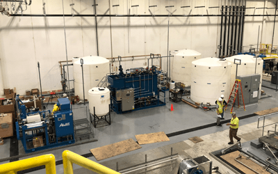 requires clean, consistent input water. Concurrently, the dirty rinse water needs to be pretreated before it can be discharged to the local Publicly Operated Treatment Works (POTW). Since this was a new line for the equipment manufacturer, Anguil assisted the manufacturer with developing specifications for:
- Input water quality (conductivity < 10 micro Siemens)
- Average input flow (30 GPM)
- Required washer input pressure
- The need for a “fast fill” mode to quickly refill the washer after maintenance activities
- The requirement for maximal equipment up time
With customer input, Anguil selected a dual train Reverse Osmosis (RO) system to meet the washer’s influent requirements.
On the wastewater side, where the exact water chemistry was unknown, Anguil again worked with the can manufacturer to determine an expected range of water contaminants to select candidate treatment technologies which could handle the variable chemistry. Expecting a pH of 2-5, high TSS loading, significant amounts of sulfuric and hydrofluoric acids, oils and greases as well as possible surfactants, Anguil proposed a form of enhanced clarification called Ballasted Flocculation (BF). With a BF system, the pH could be adjusted as needed, fluoride and other metals precipitated, and oils broken out of suspension chemically using caustic addition, coagulants and polymers. With the addition of sand to flocculated species, the settling rate increases dramatically, leading to a smaller overall equipment footprint, important since this wastewater treatment system was to be housed inside the production facility. Extra space was left in the system design to allow the addition of water polishing equipment if after start-up, it was deemed necessary.
Because Anguil is an air and water treatment supplier, Anguil was able to evaluate solutions for both treatment needs, ultimately proposing a solution that did not require air pollution control equipment. Again, this fits into Anguil being a technology agnostic solution provider always on the look-out for the customer’s bottom line.
PUTTING IT ALL TOGETHER
After determining the flow and treatment requirements for the Process Water Conditioning System (PWCS) and the Wastewater Treatment System (WWTS), Anguil proceeded to determine the required logistics equipment and controls to operate both systems in automatic mode with the least operator involvement possible.
For example, inlet water buffer and RO permeate storage tanks were selected to supply some onsite storage, ensuring back-up capacity should the city water supply fail and to provide constant, even flow to the varying washer demands. Non-metallic AODD pumps were selected to lift and convey the high solids content and corrosive waste water to the treatment system. An equalization tank and an emergency dump tank were included to buffer flow through the WWTS while providing emergency capacity if the washer needed to be dumped for maintenance reasons, and to collect additional waste water sources from sludge dewatering and secondary containment floor sumps.
In addition to the mechanical components of both the PWCS and WWTS, Anguil’s control engineers worked to integrate both the larger sub-systems (RO, ballasted floc, Rotary Vacuum Drum) into the treatment plant. More importantly, they also worked directly with the canning equipment manufacturer to seamlessly integrate the disparate washer/water treatment systems to minimize production downtime and product loss in the event of failures with the PWCS, washer system or the WWTS.
GETTING THE SYSTEM UP AND RUNNING
After obtaining customer approval of the system design, Anguil ordered the long lead-time items, namely the tanks and large third-party vendor skids. Once these items were on order, Anguil coordinated the purchase and delivery of all the parts (pumps, valves, instrumentation, etc) to be shipped loose for field installation or to be assembled on Anguil pump skids.
Since the canning equipment manufacturer had already obtained the services of installation contractors, Anguil was not engaged for a turn-key installation. However, based on our installation experience with similar systems, Anguil received, labeled each part with its PID drawing tag number, and then “kitted” all the parts into boxes to aid the installation process. For example, all the instruments, valves and piping fittings associated with a given storage tank or sub-assembly were placed in their own box. Kitting parts in this way acted as a quality control step, ensuring the correct parts and amounts were delivered, and greatly assisted the install crew as they knew exactly where and how many parts to install on each tank.
Even though Anguil was not asked to perform installation work, Anguil was hired to provide an install supervisor to interface with contractors, provide guidance where necessary, troubleshoot issues, expedite defective part replacement, communicate the project schedule and handle changing project requirements. One direct benefit of Anguil’s install supervision was the ability to respond rapidly to changing site conditions and requirements. For example, prior to processing cans, the washer system required a “passivation” step consisting of treating the washer interior with caustic and acidic waters. This requirement was not originally intended to be included in Anguil’s scope in any way. However, to assist the customer, Anguil reorganized the installation effort to enable the RO system to be run in manual mode to feed the washer and the wastewater treatment system to be run in manual mode to allow discharge and pH neutralization of the passivation water.
Special site supervision and controls workarounds were required since the equipment had not been fully commissioned and installed at the time passivation was to occur. However, Anguil’s ability to accommodate the project needs saved the customer $100,000s in disposal and transport costs of the passivation water. After can making equipment was brought online, Anguil brought in their commissioning crew to ensure that the control program was operating correctly – especially with communications between the PWCS, WWTS and washer system. This included confirming that chemical protocol was validated and optimized and ensuring that any issues discovered during the initial start-up and shake-down were addressed quickly and efficiently. Ultimately, after training the site personnel on the system operation, troubleshooting of general issues and becoming familiar with system operation, both the PWCS and WWTS were able to support the washer’s input and waste water needs with minimal operator involvement and get the packager back to what they do best—making cans.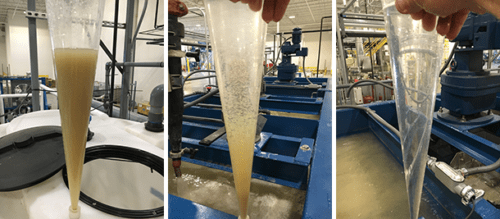
The Result
- Anguil was able to walk the customer through a collaborative treatment technology selection process resulting in systems (waste and process) that the customer was comfortable with and had high confidence would meet the desired treatment efficacy.
- Anguil’s approach of sticking to our core competency of engineering and integration led to the selection of technologies and vendors which resulted in a successful water treatment system.
- Anguil’s single source approach enabled streamlined communication when problems arouse. Instead of the customer calling multiple vendors, trying to figure out who owned the problem, they would call Anguil and Anguil led the charge as necessary. One call did it all.
- Anguil’s ability to provide both air and water treatment solutions allowed our engineering experts to explore all possible solutions and design the best fit treatment train — which ultimately removed the need for air pollution control—and lowered the total cost of ownership of the treatment system.
- Even though the customer had already contracted with installation contractors for this project, Anguil’s experience with turn-key installations made it apparent that the logistics of kitting equipment was necessary to ensure project success—all conducted within the original contract price.
- Because of the amount of pre-work done scoping the customer’s needs for both the PWCS and WWTS, no change orders were issued to complete the work—except for those items requested by the customer at a later date.
- Anguil’s customer-focused philosophy enabled us to maintain a flexible schedule to accommodate rapidly changing site demands without significant added costs to the customer.
Industrial Wastewater Treatment
Comments Off on Industrial Wastewater TreatmentThe Challenge
Anguil Environmental Systems was asked to supply an oxidizer and packed tower air stripper to treat a 65 gallon per minute water stream containing significant concentrations of Diesel Range Organics (DRO), Volatile Organic Compounds (VOCs) and Total Suspended Solids (TSS). The customer was sending the wastewater stream through a cooling tower which was continually fouling from the DRO present in the water. Significant maintenance costs and production downtime were incurred every time the tower was being brought out of service for cleaning. In addition, the customer was trying to achieve zero VOC emissions from their facility.
The Solution
Application engineers at Anguil determined that a Regenerative Thermal Oxidizer (RTO) would meet the customer’s needs but were skeptical that the air stripper would function properly given the customer supplied water characteristics. Anguil was engaged to evaluate the water stream for the air stripping application. Review of the supplied water analysis indicated that concentrations of the heavier Diesel Range Organics (naphthalene and higher) were beyond their solubility limits. Hence, the presence of free product in this water stream would quickly cause any air stripper to foul, detrimentally impacting stripping performance and potentially creating a safety hazard. Anguil recommended that the customer evaluate oil/water separation and emulsion breaking to remove and potentially recover the free product prior to entering the air stripper.
The Result
Using water samples obtained from the customer, an initial bench evaluation of oil/water separation was conducted. Upon receiving the samples, Anguil realized that either the customer-supplied water analysis was incorrect or that the water samples received were not representative of the customer’s process water since the presence of free product was not observed. The emulsion breaking tests were performed anyway, predictably meeting with little success. In addition to the emulsion breaking tests, Anguil attempted to coagulate the water to determine if this approach would be suitable, determining this method had merit.
Based on results from the initial separation study, Anguil recommended two courses of action. First, the customer would redo their analytical water analysis using suggested test methods to improve confidence in the treatment design requirements. Based on the results of the second round of analytical tests, Anguil suggested that a two stage pilot study be conducted. For Stage 1, Anguil representatives would perform treatability studies on site via jar testing. Based on the results obtained from Stage 1, Anguil engineers would perform a full scale, onsite pilot with the appropriate equipment for Stage 2.
Stage 1: Anguil representatives traveled to the site and performed jar tests directly with the process water in question. Since the process water was at a temperature of 110-120 oF, it was advantageous to work with the process directly rather than trying to ship samples off site possibly compromising their integrity from cooling, biological action or chemical reactions from long hold times. After a number of trials, they successfully determined that the water could be coagulated by raising the pH from 4 to 8.5, utilizing a poly aluminum chloride (PAC) based coagulant blend and a standard polymer. After coagulation and filtration, color, turbidity and solids content were reduced. Anguil then sent the untreated and treated water for third part lab analysis to determine the overall effectiveness of the process. The results were promising and the customer elected to move forward with Stage 2 of the pilot study.
Stage 2: Based on the site constraints and treatment goals, Anguil modified its pilot clarification system to perform the second stage of the study. Equipment arrived onsite,was unloaded and placed within the facility. A generator was rented since the facility could not easily supply the required power. Anguil then proceeded to unpack and plumb the pilot system into the existing process piping.
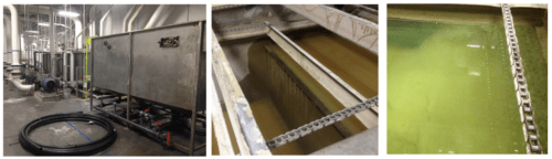
Once everything was set-up, pumps primed and running, the operator filled the tank with process water and began processing using the chemical formula determined in Stage 1: Raise pH > 8.5 using 50% caustic solution, add 300 ppm coagulant, add 1 ppm polymer. As expected, the clarifier influent demonstrated a good floc which quickly began to settle to the bottom of the clarification tank. With continued processing, clarity improvements in the clarification tank became noticeable as submerged parts of the tank became visible as the initial dirty water was displaced by the coagulated and clarified water. Water samples pulled from the clarifier effluent were obviously cleaner than the raw process water, and with continued processing acceptable clarity was achieved.
After successfully demonstrating the clarification process, treated samples were pulled and tested using the same test protocol used in Stage 1. In addition, a sludge sample was sent for benzene analysis in order to determine if the sludge would be considered hazardous. Sludge production rates were quantified by coagulating, flocculating and filtering specific volumes of process water. Filtered samples were wrung dry and air dried for several days. Wet and dried samples were weighed.
The qualitative and quantitative results met the customer’s expectations and treatment goals. The chemical coagulation protocol and clarifier in this pilot work were able achieve a DRO reduction of 85% or greater and an 80% reduction in TSS. Since Anguil was proposing a ballasted floc system for the final treatment system to handle the design flow rate of 65 GPM, another set of samples was taken for ballasted floc testing which achieved similar DRO removal rates but improved on the TSS reduction to less than 1 NTU. After reviewing the sludge production rates and potential hazardous classification for the sludge, the customer asked Anguil to recommend a sludge dewatering system. Further, after reviewing the treatment system capabilities and facility requirements, Anguil recommended removing the air stripper and oxidizer from the scope of supply as it was determined that removing the heaviest organics would solve the facilities heat exchanger fouling problems, and the limited VOC loading did not justify the use of an oxidizer.
Anguil was able to guide the customer through the equipment design and selection process by identifying and rectifying shortcomings in the analytical data, avoiding time and cost specifying and designing equipment which would not address the customer’s project goals. Ultimately, the main benefit of Anguil was determining a solution which did meet the customer’s objectives despite the fact that the selected solution differed greatly from the original request. Onsite jar and pilot tests allowed the customer to become educated and familiar with the treatment process while understanding the benefits, capabilities and trade-offs of the proposed system. Further, being on site allowed Anguil to really understand the customer’s needs and process, allowing them to identify customer process variables which could potentially affect treatment system performance and provide seamless integration of the new treatment system into the existing process.
Superfund Site, Water Pump & Treat
Comments Off on Superfund Site, Water Pump & TreatThe Challenge
Anguil was contracted as part of a team of companies to implement a groundwater pump and treat system intended to remove trichloroethylene (TCE) from a local aquifer designated as a Superfund Site by the Environmental Protection Agency (EPA). Though the site is nestled between the buildings and roadways of 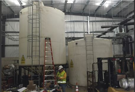 an operating industrial facility, the overall extent of the pump and treat system is expansive. Extraction wells are located over 1,000 ft. from the treatment building, with an additional 1,200 ft. of pipe run to the injection wells. All of the water treatment equipment and main control system were designed to be contained within the new treatment building, while control panels located at the extraction and injection areas were to provide local control and monitoring of the appropriate wells. Everything was to work seamlessly together.
The 500 gallon per minute (GPM) pump and treat system, as well as the overall site plan, were designed by a large engineering, procurement and construction (EPC) firm working on behalf of the responsible party. A general contractor and dedicated installation sub-contractor were selected to prepare the site, drill the extraction and injection wells, install the underground conveyance piping, erect the prefabricated treatment building, install the treatment equipment and perform all the interconnecting piping.
The Solution
Anguil was contracted for two phases of this project. During the design and approval portion, Anguil’s Electrical Engineering and Controls team was asked to review the electrical design and system controls. In addition, Anguil EEs also provided and reviewed the system controls specifications to facilitate approvals from the EPA and Army Corps of Engineers. For the construction phase, Anguil provided and managed the delivery of all the water treatment and water logistics equipment, including the control system and control panels. Furthermore, during the construction phase, Anguil field service engineers provided installation and shakedown assistance for the entire system.
Anguil’s scope of supply included all valves, process instruments and transmitters, water treatment equipment, the exhaust stack, storage tanks, pumps, chemical injection system, motor control system, main building control panel as well as two remotely located panels at the extraction and injection well sites. Further, to the largest extent possible, Anguil was directed to supply the equipment skid mounted, pre-plumbed and prewired.
The Result
Anguil was able to bring additional value to this project by successfully managing the multiple vendors of both the water treatment and controls equipment for the EPC. In particular, Anguil identified low-cost, expedited options to meet the aggressive construction schedule mandated by the EPA penalty deadlines, in some cases cutting long lead times in half. Having a custom solutions integrator on this project was especially valuable when major, unforeseen factory delays occurred. By effectively communicating with the construction team, schedules and resources were adequately adjusted. Further, Anguil was able to manage discrepancies between the selected vendor’s products and customer specifications, achieving the design specifications without sacrificing performance.
Throughout the project, Anguil provided onsite engineering assistance suggesting inexpensive changes, such as relocation of instrumentation or alternate piping plans to the equipment, which improved operations and maintenance activities. From an engineering standpoint, they were able to recommend improvements to customer specifications based on operational experience. These improvements included recommendations to upgrade materials of construction, alterations to process instrumentation, upgrading the size of the control panel touch screen to effectively display control parameters, and addition of important safety features. Furthermore, elimination of the redundant multiple control panels was accomplished by integration of logic into the Anguil supplied main system control panel. Lastly, because of site considerations, Anguil suggested substitution of the originally specified radio communications between the main control panel and remote injection well control panel with fiber optic connectivity. This ultimately resulted in a reduction of Anguil’s scope of supply, but greatly improved the system robustness and reliability.
As the project progressed, Anguil worked with the EPC engineering team on several customer-driven change orders. Most significantly, they worked with the EPC to specify and source additional flow meters for the injection well piping that were capable of accurate operation within the space constraints (limited straight run) dictated by the prefabricated concrete well vaults. Anguil managed ripple effect design changes including upgrading the effluent pump capacity, the motor control center and additional input/output cards for the local control panel – these changes were accomplished with no effect on the overall equipment delivery schedule.
In preparation of system start-up and shake down, Anguil on site personnel verified that all equipment was installed per manufacturer recommendations and was operating correctly. In several instances, they were able to identify equipment which had been installed improperly, delivered incorrectly or specified imprecisely. In most cases, these discrepancies were rectified quickly at no cost to the customer. As Anguil personnel accommodated continuing construction activities, PLC program operation was verified and altered as necessary to provide adequate system control. The final result was a turnkey system that met customer requirements for their commissioning schedule and operational characteristics so the project could start on time and on budget.
Engine Cell Exhaust: Catalytic Oxidizer
Comments Off on Engine Cell Exhaust: Catalytic OxidizerThe Challenge
Endurance testing of outboard motors for boats was typically done in lakes and sometimes on barges. It was time consuming and presented logistic problems and numerous other challenges for the research and development department at outboard motor factories. When a company in Oklahoma decided to build their own endurance test cell area, the Environmental Protection Agency (EPA) required them to control the emissions from the test engines. Four test cells were considered for air pollution abatement. The initial design exhaust volume was in excess of 4,400 SCFM (6,940 Nm3/Hr) per test cell. This high exhaust volume per cell posed a significant capital and operating cost problem when the company considered pollution control equipment.
The Solution
The company believed a thermal incinerator would be the preferred solution because of the low cost of natural gas in Oklahoma. After looking at equipment capital cost and operating costs they recognized the benefit of considering a catalytic oxidizer. After thorough technical evaluation, The customer chose Anguil Environmental Systems to solve their VOC problem and ensure that the new test cells were in EPA compliance.
The Result
Automotive catalysts have proven effective in handling exhaust gases from internal combustion engines, where both un-burned hydrocarbons and carbon monoxide are destroyed. Anguil analyzed the operation and concluded that the enclosed engine test cells needed significantly less exhaust volume than the 4,400 SCFM (6,940 Nm3/Hr) proposed. Anguil determined that the exhaust from even the largest stern drive engine was under 800 SCFM (1,262 Nm3/Hr) of air. It was critical for this to be under negative pressure, so no carbon monoxide would leak into the test facility. Using 850 SCFM (1,341 Nm3/Hr) as a design criteria, Anguil determined that a 6,800 SCFM (10,725 Nm3/Hr) catalytic oxidizer could handle the initial four test cells with the additional capacity for four future test cells.
Anguil supplied and installed the catalytic oxidizer inside the building on a mezzanine adjacent to the test area. Anguil supplied only enough catalyst to handle the initial loading from four test cells, which reduced the initial capital cost. Anguil engineers performed an exhaust stack test analysis to determine what concentration of carbon monoxide and hydrocarbons was present. The presence of carbon monoxide dictated a total enclosure around the catalytic oxidizer. Anguil placed an exhaust fan in the enclosure, creating negative pressure and eliminating the possibility of carbon monoxide leaking into the facility. The oxidizer was equipped with a variable speed/variable frequency drive to provide a high degree of turndown if only one test cell was being run. A stainless-steel plate and frame type heat exchanger was used to accommodate high exotherm across the catalyst.
Some of the engines in the facility were diesel engines and some endurance runs were lengthy. Since these engines potentially could go out of tune, a ceramic particulate filter was installed within the catalytic oxidizer down-stream of the gas burner to protect the catalyst from unburned carbonaceous materials. The periodic cycling and high fire of the gas burner eventually vaporizes these carbonaceous materials and allows them to be oxidized by the catalyst.
After approximately eight months of successful operation, the company decided to expand and add the four additional test cells. The new exhaust fans and ductwork were completed by Anguil’s installation crew and additional catalyst was added to meet the company’s increased capacity. The result is a state-of-the-art engine test facility in compliance with EPA requirements.
VAM Abatement Project in Shanxi China
Comments Off on VAM Abatement Project in Shanxi China The Challenge
 The Challenge
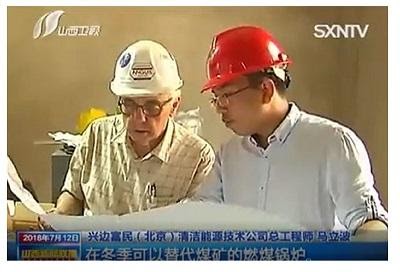
Ventilation Air Methane (VAM) refers to the ventilating exhaust from coal mines with methane concentrations between 0.1 and 1.9%. Although the concentration is extremely low, the volume of VAM flow is extremely large. Experts predict that more than 50% of all VAM is exhausted from mine ventilation systems directly to atmosphere and remains underutilized; thus the total quantity of methane released is significant. This will damage the ozone (O3) layer in the atmosphere and as a result, contribute to climate change.
The Chinese government is giving an incredible amount of attention to environmental protection and making the corresponding regulations increasingly restrictive. This has hit the coal industry hard. Almost every coal mining enterprise in China must quickly determine how to meet the regulatory standards and at the same time, efficiently utilize the huge amount of VAM.
 The Solution
 The Solution
A large coal mining company in Shanxi Province, China, decided to adopt a new technology to capture the VAM and convert it into usable energy. After careful evaluation of the suppliers, Anguil’s team in Shanghai was selected to provide the VAM air pollution control system. Anguil Environmental is headquartered in the United States with more than 1,900 pollution abatement installations around the world. Having a presence in Asia for over two decades, the company has successfully installed hundreds of their pollution abatement systems in China.
The Result
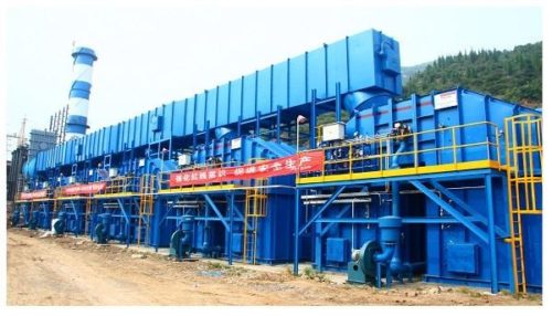
After a comprehensive design review, Anguil recommended the Regenerative Thermal Oxidizer (RTO) technology equipped with hot gas bypass to destroy the VAM emissions and some low concentration Coal Bed Methane (CMM) from the drainage pipes. With Anguil’s RTO design, no auxiliary energy is required for combustion so long as adequate incoming methane concentrations are maintained, typically above 0.35%.
Any excess heat produced during the oxidation process is routed from a hot gas bypass dampers to a boiler system to generate enough steam, which is led to the steam turbine for electricity generation. Different from traditional methods of power generation by burning the coal or gas, using the excess heat from the RTO does not result in the presence of nitrogen oxide (NOX) and can keep the hot air stream at a very stable temperature, which is very important for the following power generation. There is enough steam to also provide building heat during the winter and cooled shaft air during the summer.
This way, the RTO system is not a just destruction technology; the emissions are converted from a greenhouse gas to a revenue generating initiative for the coal mining enterprise as they are able to sell the electricity.
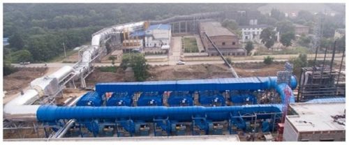
This VAM abatement project consists of six RTOs that process a total exhaust volume of 540,000 Nm3/hr (336,448 SCFM) with an average methane concentration of 1.2%. Once at full capacity, the system will generate electric power with an installed capacity of 15 megawatts which will be returned to the national power grid. Independent reports show that the methane destruction efficiency is above 99.5% and the system is capable of destroying 51 million cubic feet of methane annually.
 Under the close cooperation between the different departments and the full support from Anguil headquarters in the United States, the RTOs were installed on time and within budget. The mining customer recognized Anguil with a Best Engineering Organization Unit Award.
As a new method to utilize a very low concentration of VAM in high efficiency, this project has received extensive attention locally. As reported by several local news outlets, the initiative has been listed as a Methane Zero Net Emission Demonstration Project by China National Development and Reform Commission.
Since the success of this installation, Anguil has received several more orders from other mining companies looking to utilize VAM and reduce their environmental impact. Anguil’s VAM system proves that mining operations can profit by incorporating a properly designed oxidation technology for air purification and combine it with some sort of heat recovery system for steam, heat or electricity production.
Treating Variable VOC Loadings with Hot Gas Bypass
Comments Off on Treating Variable VOC Loadings with Hot Gas Bypass The Challenge
 The Challenge
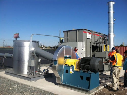
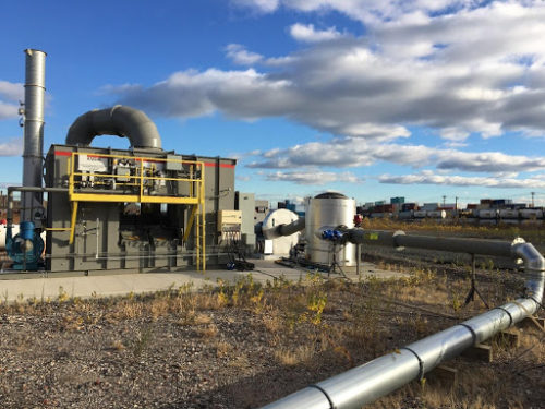
A soil and groundwater remediation firm had contacted Anguil Environmental Systems with a need to process increased Volatile Organic Compound (VOC) loading with their two Anguil Model 50 Regenerative Thermal Oxidizers (RTOs).
The Solution
The customer was experiencing high variability in VOC loading during remediation and their RTOs would shut down due to excessive temperature in the combustion chambers.
Anguil modified both RTOs to incorporate a Hot Gas Bypass, a feature designed to allow incoming process streams to have LEL levels up to 25%. HGBP diverts hot gases from the combustion chamber to the stack during high VOC loading conditions. The residence time of the diverted hot gases as they pass to the stack ensures the emissions are destroyed without affecting the system’s destruction efficiency.
Hot Gas Bypass (HGBP) is commonly ordered on new RTOs with either highly consistent VOC loading or high variability in loading. HGBP is also commonly ordered from Anguil for retrofitting onto Anguil-built RTOs and oxidizers supplied by other manufacturers.
 The Result
 The Result
Anguil retrofitted both RTOs with a new HGBP in the field. This required mechanical, rigging, and electricians onsite who were all managed by Anguil. After completion, the RTOs were able to handle the fluctuation of the customer’s process without any further high temperature shutdowns.
Quality Environmental and Energy Solutions from Anguil Environmental Systems
At Anguil Environmental Systems, we are well-equipped to provide emission abatement solutions for any industrial facility. For additional information about our capabilities and how we can benefit your company, contact us today. One of our customer service representatives will answer and address any questions or concerns you may have.
Stocking Spare Parts for Your Oxidizer System
Comments Off on Stocking Spare Parts for Your Oxidizer System OXIDIZER SERVICE SERIES: PART 3
At the risk of sounding repetitive, the same opening as Part 2 of our Oxidizer Service Series – Crafting Your Oxidizer Maintenance Plan also applies to stocking spare parts for your oxidizer system.
Many will come to this article hoping for a one-size-fits-all list for stocking spare parts for an oxidizer system. As a company that provides service for any oxidizer regardless of style or original manufacturer, we at Anguil have long wanted the same. A standardized list would certainly make life easier.
Our best recommendation for building a Spare Parts Program is as follows:
- From the documentation as listed in Part 1 of our Oxidizer Service Series – Better Maintenance Starts with Better Documentation, gather your P&ID and updated Electrical Schematics, including panel layout diagrams.
- Compile a list of your Permit Requirements, especially relating to allowable downtime each year and bypass tolerance.
- Meet with an oxidizer service provider, such as Anguil. Using the P&ID and control panel diagrams as a guide, tag each system component into one of four categories: CRITICAL, RECOMMENDED, CONVENIENCE, and ORDER AS NEEDED.
- Share the tagged diagrams with your maintenance personnel and get their feedback on whether their experiences support this categorization.
- Once the parts have been prioritized, they can be priced and purchased according to the needs of your facility. Keep in mind that many oxidizer manufacturers have OEM discounts with oxidizer component providers so they can be competitive on providing parts for your system.
- Inventory your stock once parts are purchased and on your shelves. We recommend incorporating this into your regular maintenance routine.
 Why does your Oxidizer Spare Parts Program deserve significant attention?
 Why does your Oxidizer Spare Parts Program deserve significant attention?
Consider the following:
DOWNTIME
As reliable as modern oxidizer systems can be, issues will arise with any industrial equipment. Downtime can be dramatically reduced if the right parts are available on site. What is it worth to your company if you can look back over a year and say that downtime was cut in half – or even more?
COMPLIANCE
Chances are that wording very similar to the following may already be in your environmental permit: “OPERATOR will stock the recommended spare parts as determined by MANUFACTURER.” This type of wording is being added to safety regulations governing the design and operation of oxidizer systems. Stocking appropriate levels of spare parts for your oxidizer system may be a compliance concern for your site.
DEFENSIBILITY
As mentioned earlier, problems will happen. When they do, you want to be in good partnership with your local regulatory agency. Regulators across the country are getting both tougher and smarter. If you ask for leniency in an emergency downtime situation but cannot demonstrate you’ve taken steps to stock the parts recommended by your system’s manufacturer, you may be seen as uncooperative.
PREPAREDNESS
Choosing to have a well-stocked spare parts inventory is comparable to having adequate automotive, home, or life insurance in place. Keeping the necessary components available on hand to get your system back running in a minimum amount of time is crucial. There is no lengthy downtime, lost production revenue, or plant headache due to not having the proper “insurance” in place. After all, having a stockroom full of “unused” spare parts is like having purchased several “unused” insurance policies. It is always better to have the appropriate insurance in place should it be needed.
MISSION
Anyone that owns and operates an oxidizer system has already made both a significant investment in, and a long-term commitment to, environmental compliance. Stocking an appropriate level of spare parts for your system is just one part of that same long-term commitment.
Operating Context Matters
Although we stress the importance of a well-designed thermal and catalytic oxidizers, we also consider a well-organized spare parts program crucial. As manufacturers of these systems, we take pride in the reliability of the oxidizers we build and fully expect years of trouble-free operation. As much as we want to sell spare parts packages with every oxidizer system, continuously harping on the need for a large contingent of spare parts can seem counterintuitive at times. Designing a recommended spare parts program for a particular customer can be tricky and, unfortunately, also often gets less thought than it deserves. However, there is a specific operating context that can guide the proper approach to your oxidizer spare parts plan.
Several years ago, while presenting our final proposal for an oxidizer system to a potential customer, we included a recommended spare parts package valued at approximately $20,000.00. The prospective customer was mildly put off by this number. The retort at the time was, “You mean for the amount I am spending on this equipment, I have to buy $20,000.00 worth of parts just to make sure it runs right?”
Later that same week, we attended a pre-bid meeting for another potential customer. During the review of the bid specifications, the presenter stated, “As part of your bid package for this system, we would like to see your recommended spare parts list. Fair warning, anyone that turns in a package less than $20,000.00 will get scoffed at. That would indicate you don’t understand our production situation.”
In one week we met two different potential customers, both somewhat offended by a $20,000.00 recommended spare parts package, albeit for different reasons. The kicker? Both potential customers were considering the very same model of RTO!
Happily, both potential customers did become customers. Although seemingly at odds with one another’s thinking, neither customer was technically wrong in their comments on the bid package. The first customer was not only allowed to be turned off for several months of the year but also permitted oxidizer downtime of up to ten days during the run season. The second customer was located in a non-attainment zone and only allowed up to four hours to finish a current production batch upon an oxidizer upset. At that point, all production had to stop until the oxidizer was running again.
Even though the model of oxidizer system was the same, the approach to developing a customized spare parts plan was completely different for these customers — and very permit-driven.
At Anguil, we are eager to help you in the mission of designing an Oxidizer Spare Parts Plan that is right-sized for your operating context.
This is the third of four parts in Anguil’s Oxidizer Service Series. We encourage you to also view Part 1: Better Maintenance Starts With Better Documentation as well as Part 2: Crafting Your Oxidizer Maintenance Plan and Part 4: Oxidizer System Optimization.