


Superfund Site, Water Pump & Treat
Comments Off on Superfund Site, Water Pump & TreatThe Challenge
Anguil was contracted as part of a team of companies to implement a groundwater pump and treat system intended to remove trichloroethylene (TCE) from a local aquifer designated as a Superfund Site by the Environmental Protection Agency (EPA). Though the site is nestled between the buildings and roadways of 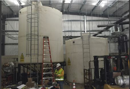 an operating industrial facility, the overall extent of the pump and treat system is expansive. Extraction wells are located over 1,000 ft. from the treatment building, with an additional 1,200 ft. of pipe run to the injection wells. All of the water treatment equipment and main control system were designed to be contained within the new treatment building, while control panels located at the extraction and injection areas were to provide local control and monitoring of the appropriate wells. Everything was to work seamlessly together.
The 500 gallon per minute (GPM) pump and treat system, as well as the overall site plan, were designed by a large engineering, procurement and construction (EPC) firm working on behalf of the responsible party. A general contractor and dedicated installation sub-contractor were selected to prepare the site, drill the extraction and injection wells, install the underground conveyance piping, erect the prefabricated treatment building, install the treatment equipment and perform all the interconnecting piping.
The Solution
Anguil was contracted for two phases of this project. During the design and approval portion, Anguil’s Electrical Engineering and Controls team was asked to review the electrical design and system controls. In addition, Anguil EEs also provided and reviewed the system controls specifications to facilitate approvals from the EPA and Army Corps of Engineers. For the construction phase, Anguil provided and managed the delivery of all the water treatment and water logistics equipment, including the control system and control panels. Furthermore, during the construction phase, Anguil field service engineers provided installation and shakedown assistance for the entire system.
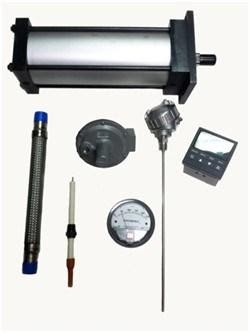
Anguil’s scope of supply included all valves, process instruments and transmitters, water treatment equipment, the exhaust stack, storage tanks, pumps, chemical injection system, motor control system, main building control panel as well as two remotely located panels at the extraction and injection well sites. Further, to the largest extent possible, Anguil was directed to supply the equipment skid mounted, pre-plumbed and prewired.
The Result
Anguil was able to bring additional value to this project by successfully managing the multiple vendors of both the water treatment and controls equipment for the EPC. In particular, Anguil identified low-cost, expedited options to meet the aggressive construction schedule mandated by the EPA penalty deadlines, in some cases cutting long lead times in half. Having a custom solutions integrator on this project was especially valuable when major, unforeseen factory delays occurred. By effectively communicating with the construction team, schedules and resources were adequately adjusted. Further, Anguil was able to manage discrepancies between the selected vendor’s products and customer specifications, achieving the design specifications without sacrificing performance.
Throughout the project, Anguil provided onsite engineering assistance suggesting inexpensive changes, such as relocation of instrumentation or alternate piping plans to the equipment, which improved operations and maintenance activities. From an engineering standpoint, they were able to recommend improvements to customer specifications based on operational experience. These improvements included recommendations to upgrade materials of construction, alterations to process instrumentation, upgrading the size of the control panel touch screen to effectively display control parameters, and addition of important safety features. Furthermore, elimination of the redundant multiple control panels was accomplished by integration of logic into the Anguil supplied main system control panel. Lastly, because of site considerations, Anguil suggested substitution of the originally specified radio communications between the main control panel and remote injection well control panel with fiber optic connectivity. This ultimately resulted in a reduction of Anguil’s scope of supply, but greatly improved the system robustness and reliability.
As the project progressed, Anguil worked with the EPC engineering team on several customer-driven change orders. Most significantly, they worked with the EPC to specify and source additional flow meters for the injection well piping that were capable of accurate operation within the space constraints (limited straight run) dictated by the prefabricated concrete well vaults. Anguil managed ripple effect design changes including upgrading the effluent pump capacity, the motor control center and additional input/output cards for the local control panel – these changes were accomplished with no effect on the overall equipment delivery schedule.
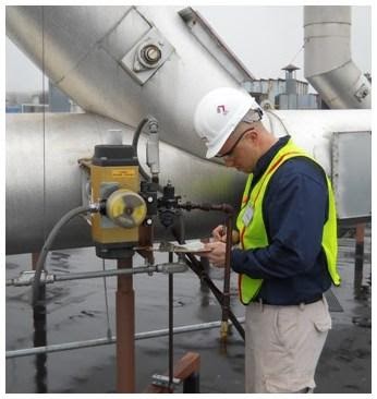
In preparation of system start-up and shake down, Anguil on site personnel verified that all equipment was installed per manufacturer recommendations and was operating correctly. In several instances, they were able to identify equipment which had been installed improperly, delivered incorrectly or specified imprecisely. In most cases, these discrepancies were rectified quickly at no cost to the customer. As Anguil personnel accommodated continuing construction activities, PLC program operation was verified and altered as necessary to provide adequate system control. The final result was a turnkey system that met customer requirements for their commissioning schedule and operational characteristics so the project could start on time and on budget.
From Open Lakes to Closed Loops: Bringing Outboard Testing into EPA Compliance
Comments Off on From Open Lakes to Closed Loops: Bringing Outboard Testing into EPA ComplianceTHE CHALLENGE
Endurance testing of outboard motors for boats typically typically involved continuous operation on closed courses, sometimes private lakes purchased by the engine manufacturers. Some of the tests could reach up to 50,000 miles to simulate years of heavy use to ensure reliability. It was time consuming, required shifts of drivers changing “on the fly,” and was performed in non-controllable environments, which could make the tests difficult to track or replicate.
When a company in Oklahoma decided to build their own enclosed endurance test modules, the Environmental Protection Agency (EPA) required them to control the emissions from the test engines. The company proposed four testing modules, all of which would require air pollution abatement. The initial design exhaust volume was more than 4,400 SCFM (6,940 Nm3/Hr) per test cell. This high exhaust volume per cell posed a significant capital investment and operating cost for the company.
THE SOLUTION
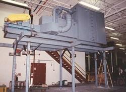
The company believed a thermal incinerator would be the preferred solution due to the low cost of natural gas in Oklahoma. However, after looking at initial equipment and operating costs, they recognized the benefit of using a catalytic oxidizer. After considering different providers, the customer chose Anguil Environmental Systems to solve their volatile organic compound (VOC) problem and ensure the new test cells were within EPA compliance.
Automotive catalysts have proven effective in handling exhaust gases from internal combustion engines, where both un-burned hydrocarbons and carbon monoxide (CO) are destroyed. After a thorough evaluation, it was concluded that the enclosed engine test modules needed significantly less exhaust volume than the 4,400 SCFM (6,940 Nm3/Hr) proposed. Anguil determined that the exhaust from even the largest stern drive engine was under 800 SCFM (1,262 Nm3/Hr) of air. It was critical for the exhaust to be under negative pressure, so no CO would leak into the test facility. Using 850 SCFM (1,341 Nm3/Hr) as a design criterion, Anguil determined that a 6,800 SCFM (10,725 Nm3/Hr) catalytic oxidizer could handle the initial four test modules. The unit was sized to have the capacity for four additional test modules in the future.
THE RESULT
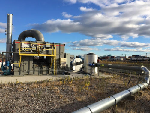
Anguil installed the catalytic oxidizer inside the building on a mezzanine adjacent to the test area. Enough catalyst was provided to handle the initial loading from four test modules, which reduced the initial capital cost. Anguil engineers performed an exhaust stack test analysis to determine what concentration of CO and hydrocarbons were present. The presence of CO dictated a total enclosure around the catalytic oxidizer. Anguil placed an exhaust fan in the enclosure, creating negative pressure and eliminating the possibility of CO leaking into the facility.
The oxidizer was equipped with a variable speed and frequency drive to provide a high degree of turndown if only one test cell was being run. A stainless-steel plate and frame type heat exchanger was used to accommodate high heat release (exotherm) across the catalyst. With the temperature increase, hot spots could form and required management to prevent catalyst degradation and provide temperature control.
Some of the engines tested in the facility were diesel and test runs were lengthy. Since these engines could potentially drift out of specification, a ceramic particulate filter was installed within the catalytic oxidizer down-stream of the gas burner to protect the catalyst from unburned carbonaceous materials. The periodic cycling and high fire of the gas burner eventually vaporized these carbonaceous materials and allowed them to be oxidized by the catalyst.
After approximately eight months of successful operation, the company decided to expand by adding four additional test cells. The new exhaust fans and ductwork were completed by Anguil’s installation crew and additional catalyst was added to meet the company’s increased capacity. Through innovation, the result is a state-of-the-art engine test facility operating safely, and in compliance with EPA requirements.
VAM Abatement Project in Shanxi China
Comments Off on VAM Abatement Project in Shanxi China The Challenge
 The Challenge
Ventilation Air Methane (VAM) refers to the ventilating exhaust from coal mines with methane concentrations between 0.1 and 1.9%. Although the concentration is extremely low, the volume of VAM flow is extremely large. Experts predict that more than 50% of all VAM is exhausted from mine ventilation systems directly to atmosphere and remains underutilized; thus the total quantity of methane released is significant. This will damage the ozone (O3) layer in the atmosphere and as a result, contribute to climate change.
The Chinese government is giving an incredible amount of attention to environmental protection and making the corresponding regulations increasingly restrictive. This has hit the coal industry hard. Almost every coal mining enterprise in China must quickly determine how to meet the regulatory standards and at the same time, efficiently utilize the huge amount of VAM.
 The Solution
 The Solution
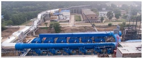
A large coal mining company in Shanxi Province, China, decided to adopt a new technology to capture the VAM and convert it into usable energy. After careful evaluation of the suppliers, Anguil’s team in Shanghai was selected to provide the VAM air pollution control system. Anguil Environmental is headquartered in the United States with more than 1,900 pollution abatement installations around the world. Having a presence in Asia for over two decades, the company has successfully installed hundreds of their pollution abatement systems in China.
The Result
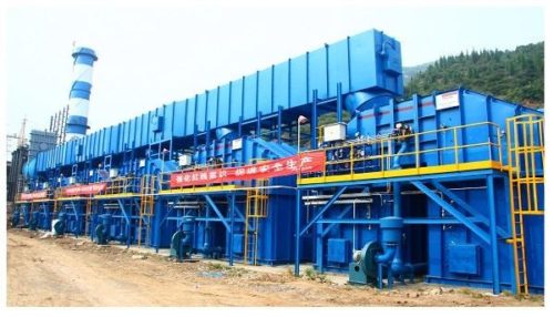
After a comprehensive design review, Anguil recommended the Regenerative Thermal Oxidizer (RTO) technology equipped with hot gas bypass to destroy the VAM emissions and some low concentration Coal Bed Methane (CMM) from the drainage pipes. With Anguil’s RTO design, no auxiliary energy is required for combustion so long as adequate incoming methane concentrations are maintained, typically above 0.35%.
Any excess heat produced during the oxidation process is routed from a hot gas bypass dampers to a boiler system to generate enough steam, which is led to the steam turbine for electricity generation. Different from traditional methods of power generation by burning the coal or gas, using the excess heat from the RTO does not result in the presence of nitrogen oxide (NOX) and can keep the hot air stream at a very stable temperature, which is very important for the following power generation. There is enough steam to also provide building heat during the winter and cooled shaft air during the summer.
This way, the RTO system is not a just destruction technology; the emissions are converted from a greenhouse gas to a revenue generating initiative for the coal mining enterprise as they are able to sell the electricity.
This VAM abatement project consists of six RTOs that process a total exhaust volume of 540,000 Nm3/hr (336,448 SCFM) with an average methane concentration of 1.2%. Once at full capacity, the system will generate electric power with an installed capacity of 15 megawatts which will be returned to the national power grid. Independent reports show that the methane destruction efficiency is above 99.5% and the system is capable of destroying 51 million cubic feet of methane annually.
 Under the close cooperation between the different departments and the full support from Anguil headquarters in the United States, the RTOs were installed on time and within budget. The mining customer recognized Anguil with a Best Engineering Organization Unit Award.
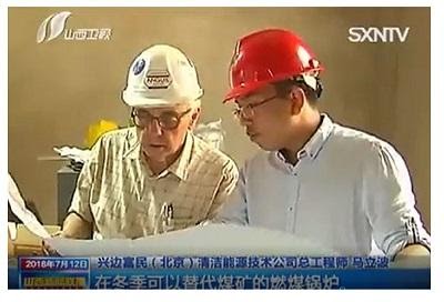
As a new method to utilize a very low concentration of VAM in high efficiency, this project has received extensive attention locally. As reported by several local news outlets, the initiative has been listed as a Methane Zero Net Emission Demonstration Project by China National Development and Reform Commission.
Since the success of this installation, Anguil has received several more orders from other mining companies looking to utilize VAM and reduce their environmental impact. Anguil’s VAM system proves that mining operations can profit by incorporating a properly designed oxidation technology for air purification and combine it with some sort of heat recovery system for steam, heat or electricity production.
Treating Variable VOC Loadings with Hot Gas Bypass
Comments Off on Treating Variable VOC Loadings with Hot Gas Bypass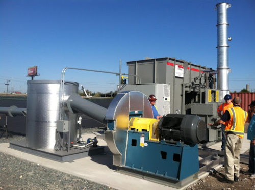
THE CHALLENGE
A soil and groundwater remediation firm was experiencing high variability in Volatile Organic Compound (VOC) loading during remediation, and their Regenerative Thermal Oxidizers (RTOs) would shut down due to excessive temperature in the combustion chambers.
THE SOLUTION
Anguil modified both RTOs to incorporate a Hot Gas Bypass, a feature designed to allow incoming process streams to have LEL levels up to 25%.
Anguil retrofitted both RTOs with a new HGBP in the field. This required mechanical, rigging, and electricians onsite who were all managed by Anguil.
THE RESULT
HGBP diverts hot gases from the combustion chamber to the stack during high VOC loading conditions. The residence time of the diverted hot gases as they pass to the stack ensures the emissions are destroyed without affecting the system’s destruction efficiency.
Hot Gas Bypass (HGBP) is commonly ordered on new RTOs with either highly consistent VOC loading or high variability in loading. HGBP is also commonly ordered from Anguil for retrofitting onto Anguil-built RTOs and oxidizers supplied by other manufacturers.
After completion, the RTOs were able to handle the fluctuation of the customer’s process without any further high temperature shutdowns.
Stocking Spare Parts for Your Oxidizer System
Comments Off on Stocking Spare Parts for Your Oxidizer System OXIDIZER SERVICE SERIES: PART 3
At the risk of sounding repetitive, the same opening as Part 2 of our Oxidizer Service Series – Crafting Your Oxidizer Maintenance Plan also applies to stocking spare parts for your oxidizer system.
Many will come to this article hoping for a one-size-fits-all list for stocking spare parts for an oxidizer system. As a company that provides service for any oxidizer regardless of style or original manufacturer, we at Anguil have long wanted the same. A standardized list would certainly make life easier.
Our best recommendation for building a Spare Parts Program is as follows:
- From the documentation as listed in Part 1 of our Oxidizer Service Series – Better Maintenance Starts with Better Documentation, gather your P&ID and updated Electrical Schematics, including panel layout diagrams.
- Compile a list of your Permit Requirements, especially relating to allowable downtime each year and bypass tolerance.
- Meet with an oxidizer service provider, such as Anguil. Using the P&ID and control panel diagrams as a guide, tag each system component into one of four categories: CRITICAL, RECOMMENDED, CONVENIENCE, and ORDER AS NEEDED.
- Share the tagged diagrams with your maintenance personnel and get their feedback on whether their experiences support this categorization.
- Once the parts have been prioritized, they can be priced and purchased according to the needs of your facility. Keep in mind that many oxidizer manufacturers have OEM discounts with oxidizer component providers so they can be competitive on providing parts for your system.
- Inventory your stock once parts are purchased and on your shelves. We recommend incorporating this into your regular maintenance routine.
 Why does your Oxidizer Spare Parts Program deserve significant attention?
 Why does your Oxidizer Spare Parts Program deserve significant attention?
Consider the following:
DOWNTIME
As reliable as modern oxidizer systems can be, issues will arise with any industrial equipment. Downtime can be dramatically reduced if the right parts are available on site. What is it worth to your company if you can look back over a year and say that downtime was cut in half – or even more?
COMPLIANCE
Chances are that wording very similar to the following may already be in your environmental permit: “OPERATOR will stock the recommended spare parts as determined by MANUFACTURER.” This type of wording is being added to safety regulations governing the design and operation of oxidizer systems. Stocking appropriate levels of spare parts for your oxidizer system may be a compliance concern for your site.
DEFENSIBILITY
As mentioned earlier, problems will happen. When they do, you want to be in good partnership with your local regulatory agency. Regulators across the country are getting both tougher and smarter. If you ask for leniency in an emergency downtime situation but cannot demonstrate you’ve taken steps to stock the parts recommended by your system’s manufacturer, you may be seen as uncooperative.
PREPAREDNESS
Choosing to have a well-stocked spare parts inventory is comparable to having adequate automotive, home, or life insurance in place. Keeping the necessary components available on hand to get your system back running in a minimum amount of time is crucial. There is no lengthy downtime, lost production revenue, or plant headache due to not having the proper “insurance” in place. After all, having a stockroom full of “unused” spare parts is like having purchased several “unused” insurance policies. It is always better to have the appropriate insurance in place should it be needed.
MISSION
Anyone that owns and operates an oxidizer system has already made both a significant investment in, and a long-term commitment to, environmental compliance. Stocking an appropriate level of spare parts for your system is just one part of that same long-term commitment.
Operating Context Matters
Although we stress the importance of a well-designed thermal and catalytic oxidizers, we also consider a well-organized spare parts program crucial. As manufacturers of these systems, we take pride in the reliability of the oxidizers we build and fully expect years of trouble-free operation. As much as we want to sell spare parts packages with every oxidizer system, continuously harping on the need for a large contingent of spare parts can seem counterintuitive at times. Designing a recommended spare parts program for a particular customer can be tricky and, unfortunately, also often gets less thought than it deserves. However, there is a specific operating context that can guide the proper approach to your oxidizer spare parts plan.
Several years ago, while presenting our final proposal for an oxidizer system to a potential customer, we included a recommended spare parts package valued at approximately $20,000.00. The prospective customer was mildly put off by this number. The retort at the time was, “You mean for the amount I am spending on this equipment, I have to buy $20,000.00 worth of parts just to make sure it runs right?”
Later that same week, we attended a pre-bid meeting for another potential customer. During the review of the bid specifications, the presenter stated, “As part of your bid package for this system, we would like to see your recommended spare parts list. Fair warning, anyone that turns in a package less than $20,000.00 will get scoffed at. That would indicate you don’t understand our production situation.”
In one week we met two different potential customers, both somewhat offended by a $20,000.00 recommended spare parts package, albeit for different reasons. The kicker? Both potential customers were considering the very same model of RTO!
Happily, both potential customers did become customers. Although seemingly at odds with one another’s thinking, neither customer was technically wrong in their comments on the bid package. The first customer was not only allowed to be turned off for several months of the year but also permitted oxidizer downtime of up to ten days during the run season. The second customer was located in a non-attainment zone and only allowed up to four hours to finish a current production batch upon an oxidizer upset. At that point, all production had to stop until the oxidizer was running again.
Even though the model of oxidizer system was the same, the approach to developing a customized spare parts plan was completely different for these customers — and very permit-driven.
At Anguil, we are eager to help you in the mission of designing an Oxidizer Spare Parts Plan that is right-sized for your operating context.
This is the third of four parts in Anguil’s Oxidizer Service Series. We encourage you to also view Part 1: Better Maintenance Starts With Better Documentation as well as Part 2: Crafting Your Oxidizer Maintenance Plan and Part 4: Oxidizer System Optimization.
Oxidizer System Optimization
Comments Off on Oxidizer System Optimization OXIDIZER SERVICE SERIES: PART 4
As promised, this is the fourth installment of Anguil’s Oxidizer Service Series. Having all the proper documentation, a strong service plan, and recommended spare parts stocked will not only improve your system performance but also allow the focus to shift to optimizing your oxidizer efficiency. Setting all these aspects in place within your maintenance plan aids in a proactive approach to ensuring your system’s reliability.
However, the above does not consider the daily running cost. How much is your oxidizer costing you to operate? How much should it cost to run if it’s running efficiently? A fully optimized oxidizer will save money on operating costs, reduce greenhouse gas footprint, and contribute to the bottom line in very measurable ways.
Oxidizer system optimization can fall into two categories: The first is “reactive,” meaning you identify and respond to the small inefficiencies that occur over the life of an oxidizer system as they happen. The second is “proactive.” This is when you act proactively, preemptive maintenance plan and regular testing of the system.
Things to Consider:
- Over the course of a year, unnecessarily treating an additional 1,000 SCFM (1,605 Nm3/hr) of process exhaust in an oxidizer system can cost upwards of $10,000 with a regenerative thermal oxidizer (RTO) and over $30,000 for a thermal recuperative oxidizer (TR) system.
- Making a modest improvement in the thermal energy recovery (TER) of an RTO system — even as little as 1% — can cut natural gas bills by 20% or more.
- Most emission abatement systems are designed and installed based on a theoretical projection of future production levels, often with a safety factor included. If an oxidizer remains at a facility for 15 to 20 years, as many do, it is very unlikely that an existing system is optimized for current production conditions, emission characteristics, and process demands.
Plant managers should periodically review the operating costs associated with their oxidizer system. This regular review will allow for informed decisions about both reactive and proactive efforts, translating directly into lower operating costs. If PMEs or testing of the oxidizer are routinely required, and included in your maintenance plan, this is an excellent time to schedule an operating cost review.
Operating costs can be reviewed during monthly — or even weekly — walk-by inspections and checklists. These inspections are typically performed by your own personnel. However, Anguil can provide you with a checklist for “Monthly Maintenance Day” inspections of the system components needing inspection, independent verification, and/or calibration monthly. As your in-house maintenance personnel learn and perform checks on their own, more money is saved, and your system will run more efficiently.
 Optimization Strategies
 Optimization Strategies
What follows are some general strategies for oxidizer optimization, applicable to a wide range of system types. With limited information, an oxidizer company like Anguil can quickly determine which of the following strategies would be a good fit for you.
KNOW HOW MUCH YOUR OXIDIZER IS SUPPOSED TO COST TO OPERATE
Make sure you can answer the following questions:
- What is the expected annual operating cost of our oxidizer?
- How close is our actual operating cost to that expected value?
With relatively minimal inputs, oxidizer vendors can run a performance model and give you the expected operating cost range for your system.
PAY ATTENTION TO THE PERCENTAGES
After five years of operation, an RTO originally designed for 95% TER could easily slip to 93% TER. While a two percent decrease might not sound like a big deal, that decrease in TER actually equates to a 40% increase in natural gas consumption. Percentage points do accrue over the course of a year, so get to know the critical parameters to watch as your system ages.
KNOW YOUR EMISSION LOADING – ESPECIALLY THE AMPLITUDE AND DURATION OF PEAKS
The size of an oxidizer is almost always determined by the peak emission levels coming from an application, but it is the average emission loading that dictates operating costs. Estimates for future “worst case scenarios” are made in the design phase to ensure a system is not undersized. After a couple of years of operation, assess the day-to-day production loading to ensure you are not operating an oxidizer designed to handle a peak loading which you would never reach.
KNOW WHAT OXIDIZER SYSTEM WOULD BE SPECIFIED FOR YOUR PROCESS TODAY
Vapor combustion technologies have evolved over the years. Knowing what is specified for your application in today’s energy-conscious market can indicate cost effective upgrades to existing equipment. Alternatively, an entirely different oxidation technology may be better suited for your application today. Knowing what is currently available can save you from investing too much money into a non-optimized oxidizer system.
IMPROVE PRIMARY HEAT RECOVERY
Oxidizers are typically designed with internal heat recovery. Usually, the primary heat recovery of an oxidizer system is when hot purified gases leaving the combustion chamber are used to pre-heat the incoming solvent-laden air stream. Projects improving the primary heat recovery of an oxidizer system offer the quickest payback because they always provide additional heat recovery while the oxidizer is in service. For example, a coating company increased the primary heat recovery in their RTO and the system is now self-sustaining, meaning no supplemental fuel is required during most operating conditions.
CONSIDER SECONDARY HEAT RECOVERY
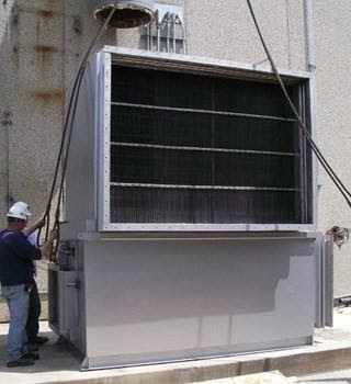
If improving primary heat recovery is not cost effective or oxidizer operating conditions do not allow it, secondary heat recovery may be the next best option. Heat exchangers can be added to the exhaust stack of an existing oxidizer to capture excess heat in air, water, or even steam. There are a wide variety of low backpressure designs that can be added to an oxidizer’s stack without requiring a replacement of the oxidizer system fan. See our Oxidizer Energy Recovery Options article for an in-depth look at this optimization strategy.
 FOCUS ON COMBUSTION AIR
 FOCUS ON COMBUSTION AIR
Combustion air, in both your oxidizer system and process burners, is often overlooked as a potential area for operating cost savings. Confirming the burners are tuned properly and only fire when necessary can make a big difference. With RTOs, there is an additional opportunity to install flameless supplemental fuel injection (SFI) systems where combustion air is not needed. Retrofit options that utilize a heat exchanger to supply combustion air from the chamber or stack are also available.
INVESTIGATE AN EMISSION CONCENTRATOR
Fuel usage for most thermal and catalytic oxidizers will decrease as emission levels increase. If a significant portion of the process air being treated is near ambient temperature with low levels of contaminants, an emission concentrator may be an option for your facility. Often utilized on paint booths and floor sweeps, this technology can absorb emissions and convert them into a smaller, more fuel-rich air stream that reduces the heat input required by a combustion device. Concentrators can increase the capacity of an oxidizer by a factor of eight to 25 when added upstream of an existing system.
KNOW WHAT GRANT MONEY IS AVAILABLE TO YOU
Energy reduction upgrades to existing equipment have an initial investment cost. These expenses can often be supplemented with grant money from utility companies if there is a significant reduction in fuel usage and/or electrical consumption. Know what grant money is available to you, whom to contact, when, and how to apply. Anguil routinely partners with our customers to secure grant money on applicable projects. We have found the Database for State Incentives for Renewables & Efficiency (DSIRE) to be a great resource.
PROPERLY MAINTAIN EXISTING SYSTEMS
No matter how well an abatement system is designed and manufactured, it cannot continue to operate at high efficiency levels without maintenance. Small inefficiencies in system operation can lead to large operating expenditures over the course of a year. While a formal maintenance plan with checks and balances is ideal, it is often not feasible. However, as noted in part two of the Oxidizer Service Series on Crafting Your Oxidizer Maintenance Plan, there are basic service guidelines which can help improve running time, keep you in compliance, and reduce operating costs. With today’s energy prices, a regular service schedule can pay for itself many times over.
Anguil has written extensively on oxidizer operating cost reduction strategies. For more in-depth information that is not included in these optimization suggestions, view the full version of Anguil’s Operating Cost Reduction Strategies.
This is the fourth and final installment in Anguil’s Oxidizer Service Series. We encourage you to also view Part 1: Better Maintenance Starts With Better Documentation, Part 2: Crafting Your Oxidizer Maintenance Plan and Part 3: Stocking Spare Parts for Your Oxidizer System.
The Modernization Mandate: Optimizing Performance with Media and Controls
Comments Off on The Modernization Mandate: Optimizing Performance with Media and Controls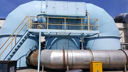
THE CHALLENGE
A 25-year-old three-chamber regenerative thermal oxidizer (RTO), originally manufactured by Smith Engineering, was beginning to show its age to its major wall manufacturing owner. Anguil Environmental Systems was brought in to optimize and modernize the equipment.
It was discovered the media was not working as well as it could, and the electronic control system was starting to be difficult to maintain. The customer’s goal was to extend the life of the unit, increase VOC destruction, and cut back on increasing operating costs.
THE SOLUTION
The first repair was to replace the oxidizer’s aging ceramic media with high-performance extruded monolith block media. This simple change instantly boosted thermal energy recovery (TER) while maintaining top-tier volatile organic compound (VOC) destruction. This easy change resulted in over $250,000 in annual energy savings.
To further improve efficiency, Anguil optimized airflow distribution through the media using perforated stainless-steel sheets in the cold face. This change ensured uniform air distribution, improved thermal performance, and consistent VOC destruction. Insulation repairs and replacements eliminated exterior hot spots for safer, more stable operation.
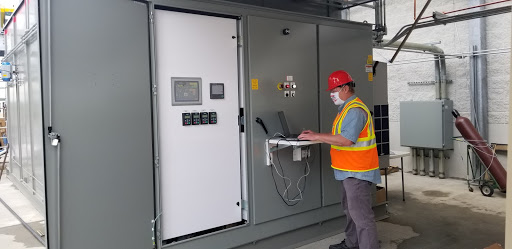
Recognizing that the old control system was becoming a maintenance nightmare, and out of date with current technology, Anguil installed a state-of-the-art control panel featuring a new PLC, HMI, VFDs, and Ethernet-based remote access. This upgrade provided operators real-time visibility, smarter control, and easier troubleshooting. Remote access is a gamechanger in the industry as it allows experts to execute repairs without the associated costs of an on-site visit.
THE RESULT
With these optimizations, the RTO now runs smoother, cleaner, and cheaper. The new media reduced operating costs while the modern control panel gives the customer modern components and complete control of their equipment.
Operating Cost Reduction Strategies
Comments Off on Operating Cost Reduction Strategies The Challenge
 The Challenge
More and more, companies operating air pollution control equipment today realize that the initial capital cost of an oxidizer system can be rapidly eclipsed by continued operating expenses if careful attention is not periodically given to the system.
The Solution
Below are ten tips to ensure your oxidizer is operating at peak performance. The first five tips focus on parameters end-users should know about their oxidizer systems, while the last five address energy reduction projects to be considered.
The Result
1. Know how much your oxidizer is supposed to be costing you to operate.
It is surprising how many facilities cannot answer the following two questions.
- How much is our oxidizer operation expected to cost?
- How close is our oxidizer operating to that expected value?
The “out of site, out of mind” approach is entirely too prevalent when it comes to air pollution control equipment. While that speaks highly for the reliability of systems installed today, it also hints at a blind spot around the day-to-day operating cost of oxidizer systems. With relatively minimal inputs, oxidizer vendors can run a performance model for you and give you the expected operating cost range for your oxidizer system.
2. Pay attention to the percentages.
After five years of operation, a Regenerative Thermal Oxidizer (RTO) originally designed for 95% TER (Thermal Energy Recovery) may have slipped to 93% TER. This might not sound like a big deal, and this may go unnoticed by even the most attentive maintenance department. However, an average sized RTO (25,000 SCFM, 40,125 Nm3/hr) operating for a full year at 93% TER versus 95% TER could cost upwards of an additional $65,000.00 a year! Percentage points do count over the course of a year. Get to know the critical parameters to watch as your system ages.
3. Know your VOC loads – especially the amplitude and duration of peaks.
Often it is peak VOC (Volatile Organic Compound) loads that determine your oxidizer design, but average VOC loads that determine your oxidizer operating cost. When an oxidizer is specified, designed, and installed, oftentimes it is the anticipated VOC loading peaks that dictate the amount of heat recovery incorporated. Typically, estimates for a future “worst case scenario” are made to ensure a conservative approach is taken. After a couple years of operation, it may be time to examine whether the design was too conservative and the peak solvent usage is much lower than originally estimated. Operating an oxidizer designed to handle a theoretical peak loading may be costing you much more than necessary for your actual day-to-day production loading.
4. Know what oxidizer system would be specified for your process today.
Finding out exactly what would be specified to treat your process exhaust today is a valuable exercise, especially if your existing equipment is in need of significant repairs or upgrades. Knowing what would be specified in today’s energy conscious market can serve to illuminate cost effective upgrades to your existing equipment.
For instance, five to 10 years ago, an RTO with 90% heat recovery may have been specified to treat your process exhaust. Today, oxidizer vendors may prescribe an RTO with 95% or 96% heat recovery and a hot gas bypass damper to deal with high VOC loading periods. If your existing oxidizer system is due for repairs, a service provider such as Anguil can also determine whether it would be cost effective to upgrade to today’s standards at the same time.
Alternatively, it may be a completely different oxidation technology specified today. With today’s control schemes, RTOs have expanded their applicability greatly over past years, while also dropping significantly in initial capital cost. Knowing exactly what would be specified today can save you from sinking too much money into an outdated oxidizer system.
5. Know what grant money is available to you.
Energy reduction upgrades to existing equipment will have an associated initial capital cost. This can be significantly reduced with grant money from local utility companies. Across the country, money has been earmarked for the specific purpose of funding energy reduction projects. Know what grant money is available to you, whom to contact, and when and how to apply. The main intent of these programs is to take upgrade projects that you (or your management) may be on the fence about and contribute the funds necessary to make them very attractive.
6. Concentrate high volume low VOC airstreams prior to oxidizer.
If a significant portion of the air entering your oxidizer is at or near ambient temperature with low levels of VOC loading, a VOC concentrator may be applicable for reducing the heat input required by your oxidizer system.
As a result of recent regulations, many facilities around the country have been forced to improve localized VOC capture as well as prove high destruction efficiency in their oxidizer system. In many cases, this has led to the installation of additional capture hoods or enclosures and increased the amount of air to be treated by a particular oxidizer system. A concentrator can take exhaust air at or near ambient temperatures and concentrate it so that what is actually sent over to the oxidizer system is reduced by a factor of eight to 15 times. This greatly reduced airflow is typically fuel-rich with VOCs and much less of an operating cost burden on the oxidizer system.
7. Focus on combustion air.
Combustion air, both in your oxidizer system or in your process burners, is often overlooked as a potential area for operating cost savings. Next to the main oxidizer system fans, the smaller combustion fan supplying high-pressure air across the oxidizer burner can seem insignificant. However, these smaller fans, more often than not, are supplying fresh air at outdoor temperatures directly into the oxidation chamber where it must be heated to full oxidation chamber temperature. At a temperature difference usually over 1400 F, it does not take much airflow over the course of a year to add up to significant operating cost dollars.
Making sure burners are tuned properly and not firing on excess combustion air can make a big difference. With RTOs, there is the additional opportunity to install a flameless fuel injection system where combustion air is not needed at all. Finally, even with a perfectly tuned burner, combustion air can be preheated using a heat exchanger or a blend with stack air.
 8. Improve primary heat recovery.
Oxidizers are typically designed with some form of internal heat recovery. Usually the hot purified gases leaving the combustion chamber are used to pre-heat the incoming pollutant-laden airstream. This is referred to as the Primary Heat Recovery of an oxidizer system. Projects that improve the primary heat recovery of an oxidizer system often offer the quickest payback because they provide additional heat recovery at all times the oxidizer is in service. For recuperative thermal and catalytic units, this typically consists of adding additional passes to the internal air-to-air heat exchanger. For RTOs and RCOs this would be handled with increasing or changing the type of ceramic heat recovery media or changing the control scheme that dictates how often beds are switched from inlet to outlet.
9. Consider secondary heat recovery.
If improving primary heat recovery is not cost effective, or oxidizer operating conditions do not allow it, secondary heat recovery may be the best option for utilizing the energy output of the combustion process within an oxidizer system. Heat exchangers can be added to the exhaust stack of an existing oxidizer to capture excess stack heat in air, water, or even steam. There is a wide variety of low back-pressure designs that can be added to an oxidizer’s stack without requiring a replacement of the oxidizer system fan. Direct-fired and thermal recuperative designs often offer the most potential payback for add-on heat recovery systems.
Payback for these projects is greatly improved if the captured heat can be used back in the exhaust generating process itself, because again, it is assumed that the process is operating at all times the oxidizer is operating. For example, fresh air is passed through a secondary heat exchanger in an oxidizer exhaust stack and supplied back as base loading for the oven zones the oxidizer is treating. Every time the oxidizer is on the oven zones require heat, so this heat recovery project pays back all year long. If the same fresh air was supplied back to the plant as tempered makeup air, this may only provide payback during the heating season.
Following this logic, in the past comfort heat applications may have been ignored. But considering today’s unstable and rising fuel costs, coupled with the energy recovery grants available to facilities, these projects deserve attention.
10. Properly maintain existing systems.
Finally, no matter how well an overall system is designed, it cannot continue to operate at a high efficiency level without proper maintenance. A handful of small inefficiencies in system operation can lead to large operating cost bills over the course of a year. At today’s energy prices, regular calibration of feedback instruments and control loops can pay for itself many times over.
All too often, production facilities take the “No News is Good News” approach to their air pollution control equipment when they really should be chasing the benefits of “Company Stays Green and Saves Green” headlines instead.
New Media Makes RTO Natural Gas Usage a Rarity
Comments Off on New Media Makes RTO Natural Gas Usage a Rarity
THE CHALLENGE
Tekra, a custom coater of plastic films in Wisconsin, has always had an eye for energy conservation. State regulations in Wisconsin require an over 98% destruction rate of volatile organic compounds (VOCs). While many companies simply abide by that regulation, Tekra takes it steps further in their exhaust process.
While considering their first oxidizer system, Tekra’s Engineers did their research and selected an early model regenerative thermal oxidizer (RTO). While RTOs were an investment, Tekra knew that long-term, it was their best choice for reliable air pollution control, lower operating costs, and a smaller carbon footprint. “We have always tried to be a green company,” said Zachary Gernetz, Project Engineer for Tekra.
In 2003 it was time for Tekra to replace their aging RTO system, and they turned to Anguil Environmental Systems. The equipment of choice was again an RTO, although Anguil’s RTO had significant advantages over the previous model including: 95% thermal energy recovery (TER), lower horsepower and operating temperatures, as well as better options for turndown and idle modes.
“Tekra went so far as to have us install a small odometer-style meter right on the front of the control panel for the Anguil RTO, showing exactly how many BTUs, they were saving over their previous unit,” says Greg Blando, former Service Manager for Anguil.
THE SOLUTION
Thermal efficiency of an RTO relates to the ceramic media inside the oxidizer which captures and then releases energy to pre-heat the incoming, untreated airstream.
Tekra’s focus on achieving energy efficiency did not stop in 2003. With a reinvigorated nationwide focus on green business practices, and energy costs on the rise, they again challenged Anguil to perform even better in 2009. Anguil studied the temperature charts of the RTO system and took air samples during peak VOC loading production runs. Using that data, it was determined that the 95% TER of the system could be pushed closer to 97% without creating any adverse high-temperature conditions in the RTO.
“A two percent improvement in TER may not sound all that impressive,” says Mike Scholz, Project Engineer for Anguil. “But most RTOs out there today were designed to achieve about 95% TER. The natural gas required by those systems is directly tied to five percent of energy lost. Getting back two of the lost five percent is a 40% reduction in energy lost. In practical terms, that two percent improvement in TER can translate into 40% less on your RTO natural gas bill.” In addition, the enhanced performance at Tekra put their oxidizer into a self-sustaining mode more often, meaning the fuel value in the VOC-laden exhaust gases are enough to operate the RTO and no auxiliary fuel is needed, hence fewer greenhouse gases are emitted.
THE RESULT
As advances in RTO ceramic heat recovery media happen, Anguil is routinely able to provide RTO operators like Tekra with a performance upgrade. The upgrade is achieved by either adding to the top of existing media beds or at times replacing the top layers of existing beds with new extruded ceramic media blocks.
“With this type of project, payback is king,” comments Lee Kottke, a manufacturer’s rep for Anguil closely involved in the Tekra relationship. “That’s why it is exciting that Anguil can achieve this level of success with only partial media change-outs. That keeps the project cost down and payback periods very reasonable.”
There are other possible influences to consider. Deeper media beds may require the relocation of chamber instrumentation – like thermocouples. Also, higher efficiency media styles can come with increased back pressure and electrical horsepower cost. Often, however, as in the case of Tekra’s RTO, the electrical use is minor compared to the natural gas savings.
Tekra confirmed that with two coaters running a variety of coating weights and line speeds, it is difficult to get an exact dollar savings. However, prior to the media replacement, their RTO often required natural gas to maintain temperature when only treating the exhaust from one coating line. Post retrofit, “the RTO rarely requires natural gas even when only one coater is operating and never when both are on,” says Gernetz. Zach added, “Jobs that were never self-sustaining before are now. So, I know that the media retrofit is saving us money.” He estimates a two year payback for this retrofit.
Considering some enhancements to your RTO? Think about this:
- Up until recently, most RTOs were designed with 95% thermal energy recovery (TER) or less.
- Rule of Thumb for self-check: If the average RTO outlet temperature is more than 100°F higher than the RTO inlet temperature, your actual TER is probably less than 95%.
- Even a small increase in TER can have a dramatic effect on RTO fuel usage. In some cases, a bump in TER could eliminate RTO fuel use entirely.
- Advances in ceramic media have allowed Anguil to improve TER in RTOs by only replacing a portion of the existing ceramic media beds, improving payback periods.
- Anguil has performed this retrofit on numerous RTOs, regardless of original manufacturer, and offer free savings analysis for those interested.
According to Chris Anguil, President of Anguil Environmental Systems, Inc, “When I reflect on the relationship between Anguil and Tekra, it strikes me how RTOs, while such a huge leap forward in energy efficiency over previous oxidizer styles, are continuing to evolve. Advances in media and controls mean there is still room for efficiency improvements on any RTO system out there, regardless of age. Anyone who owns an RTO should follow Tekra’s lead and continue to ask if they can do even better energy efficiency-wise. We applaud Tekra’s commitment to environmental compliance and energy efficiency and thank them for challenging us with this opportunity.”
Compliance Without Compromise: Increasing Oxidizer Capacity by 80,000 SCFM
Comments Off on Compliance Without Compromise: Increasing Oxidizer Capacity by 80,000 SCFM
THE CHALLENGE
A recreational equipment company bought a three-year-old manufacturing facility that happened to have an existing regenerative thermal oxidizer (RTO), for production of their outboard engines. They required emission control equipment to manage the volatile organic compounds (VOCs) emitted by the solvents used in the engine painting processes. The company wanted to minimize overall costs by utilizing the existing RTO to control their emissions. The multiple paint spray booths and ovens producing 80,000 SCFM (128,400 Nm³/hr) of exhaust air, an impossible challenge for the existing RTO, which had been designed and built to control only 17,000 SCFM (27,285 Nm³/hr).
THE SOLUTION
Anguil’s engineering team created a solution that allowed the company to utilize the smaller RTO inherited with the building. By placing two 40,000 SCFM (64,200 Nm³/hr) rotor concentrators upstream from the RTO, the company could cost-effectively expand their operation and still achieve regulatory compliance.
Controlling the high-temperature oven exhaust alone would have ruled out VOC adsorption technologies. However, by combining booth and oven exhausts, Anguil implemented an integrated VOC concentrator/oxidizer system that reduced the total exhaust flow from 80,000 to 8,000 SCFM.
The spray booth and oven exhausts were routed through a concentrator system where VOCs were adsorbed onto zeolite-coated honeycomb media. The VOCs were then desorbed from the concentrator wheel using an airflow one-tenth of the original volume. This led to the VOC concentration being approximately 10 times higher than the initial air stream. This smaller, more concentrated stream was treated in the oxidizer. This significantly reduced both capital expenses and operating costs.
Many concentrator/oxidizer systems use oxidizer exhaust heat for desorption; the RTO’s high efficiency resulted in a low outlet temperature unsuitable for heat recovery. To maintain energy efficiency and performance, a dedicated heat source was installed specifically for the concentrator desorption.
THE RESULT
The existing RTO required mechanical and electrical upgrades to allow for the integration of the concentrator. Anguil’s modification minimized the overall project cost and delivered the following benefits:
- Increased process capacity: Low desorption flow enabled the connection of additional process lines to the existing RTO.
- Automated integrated controls: Controls were designed for insurance and safety compliance, with remote telemetry for monitoring.
- Extended equipment life: Re-insulation of the RTO eliminated hot spots.
- Improved VOC destruction: Repairs to valves reduced leakage, and control valve captured/oxidized the VOC “spike” typical of two-chamber RTO installations.
- Lower operating costs and emissions: Supplemental fuel injection (SFI) reduced auxiliary fuel needs and significantly cut NOx output.