





How to Properly Maintain and Service Your Oxidizer
Comments Off on How to Properly Maintain and Service Your Oxidizer The Challenge
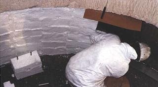 The Challenge
Your air pollution control system represents a significant investment in not only initial capital but also ongoing maintenance and operation. Routine inspections performed by your staff combined with thorough maintenance plans provided by Anguil Environmental Service Technicians will ensure you get the most from your investment over the entire life of the system. Anguil has almost four decades of experience servicing a full range of oxidizer technologies, regardless of manufacturer, make or model. Following the recommendations made below will help keep your system operating both efficiently and effectively, reducing costly repairs and avoiding downtime.
The Solution
ROUTINE INSPECTIONS:
It is our goal here at Anguil to provide owners of our equipment the necessary checklists and training to comfortably perform the routine inspections with their own personnel. In the event you own another manufacturer’s equipment the checklist below may vary slightly.
Inspections include a combination of equipment checks on the “high use” items and data recording to build a history of unit performance. When performing equipment checks, operators should refer to manufacturer’s O&M Manuals for detailed procedures. For the data-gathering items, refer to historical data and note any significant changes from typical values.
WEEKLY MAINTENANCE CHECKS – TO BE PERFORMED BY THE LOCAL MAINTENANCE STAFF OF THE EQUIPMENT OWNER/USER.
- Examine air inlet filters for dirt and obstruction, clean or replace as necessary.
- Check to ensure all fan/motor guards are in place and properly secured.
- Prior to operating the system, ensure that all oxidizer doors and access panels are closed and latched.
- Check the fan(s) mounting bolts to ensure they have remained tight.
- Perform a visual inspection of the oxidizer for any loose hardware or damper linkage.
- Visually inspect the oxidizer surface looking for any new “hot-spots” which may be identified by burnt paint and other signs of overheating found on the oxidizer shell or valve housing.
- During the oxidizer’s normal operation, check for fan vibration, abnormal sounds or increased noise levels.
- Visually inspect and listen for unusual sounds during valve operation. Valves should shift smooth and evenly in both directions.
- Inspect the oxidizer fuel train for leaks or loose hardware.
- Check all temperature device read-outs to confirm temperature operation is within normal ranges.
- View pressure device read-outs to confirm operation is within normal range.
- Verify temperature chart recording device is “On” and recording data.
MONTHLY MAINTENANCE CHECKS – TO BE PERFORMED BY THE LOCAL MAINTENANCE STAFF OF THE EQUIPMENT OWNER/USER.
- Check the burner linkage and external burner components for wear or signs of loosening that could cause gradual slipping and adjustment issues with gas and air settings.
- Check fan drive belts for correct alignment, alignment and wear. The belts should have enough tension to allow only one-half-inch movement when pushed or pulled, up or down by hand. A quick check for alignment can be done by testing the tension on the inner and outer belts. The tension should be equal.
- Remove all pressure switch sensing lines, or open drain valves if available, to ensure they are clear and dry.
- Process air and exhaust fan/motor bearings should be greased, per manufacturer’s recommendation. Rotate the shaft slowly by hand while applying the grease. Avoid over-greasing as it can damage the bearing seals.
- Drains or weep holes on all fan motors should be checked for debris and cleaned as necessary.
- Verify oil level of compressed air lubricator, add as necessary.
- Verify burner flame visually at burner or system Peep-Sight for color and intensity. The flame should typically be “Blue” with “Orange/Yellow” tips. The flame strength should not be “Lazy”, you should verify intensity at several different firing rates.
 SEMI-ANNUAL MAINTENANCE CHECKS – CAN BE PERFORMED BY MAINTENANCE STAFF OF THE EQUIPMENT OWNER/USER OR AN ANGUIL ENVIRONMENTAL SERVICE TECHNICIAN.
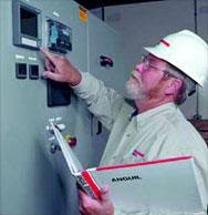 SEMI-ANNUAL MAINTENANCE CHECKS – CAN BE PERFORMED BY MAINTENANCE STAFF OF THE EQUIPMENT OWNER/USER OR AN ANGUIL ENVIRONMENTAL SERVICE TECHNICIAN.
- The interior of the oxidizer should be inspected. While inside, inspect the insulation for signs of deterioration, damage or gaps. Use extreme caution when entering or exiting the oxidizer to avoid damaging the door or the door threshold insulation (if applicable). Internal entry to be made by qualified personnel per site safety requirements.
- Clean the inner lens of the burner view port with a soft, dry cloth.
- Check the ceramic media for buildup of particulate or residue and visible damage.
- Before closing access doors, inspect the gaskets replacing or repairing as necessary to maintain a leak free seal.
- Visual inspection (only) of poppet valve shafts, seats, and disks. Caution: This should be performed by trained / authorized personnel only, after adhering to all lock-out / tag-out safety precautions. Note:The flow control valves may shift without warning if the mechanical safety pins are not installed.
- Remove the UV scanner and clean the view lens with a lint free cloth.
- Replace the spark igniter.
- Inspect the exterior of the burner for damage or areas showing excessive heat.
- Inspect all fan flex joints and replace as necessary
- The T-dampers and linkage (if applicable) should be inspected for proper operation and the linkage checked for tightness and lubrication at appropriate points.
- Verify burner flame visually at burner or system Peep-Sight for color and intensity. The flame should typically be “Blue” with “Orange/Yellow” tips. The flame strength should not be “Lazy”, you should verify intensity at several different firing rates.
- Review past alarms for identification of areas requiring specific attention to eliminate possible future alarms.
YEARLY INSPECTION: PREVENTIVE MAINTENANCE EVALUATIONS (PMES):
The Anguil Preventive Maintenance Evaluation (PME) is a two to three day thorough evaluation of your system performed by a qualified Anguil Field Service Engineer. Typically, PMEs are scheduled on an annual or semi-annual basis. It does require the system be cooled down and not running for one day to complete the internal inspection. On the second day of a PME the availability of process airflow is recommended in order for the system to be inspected under normal operating conditions.
The inspection is based upon a comprehensive checklist followed up with a written formal report for your records. The formal reports are an important component of a proper maintenance / record-keeping program and are often very helpful when working with local regulatory agencies. In some cases, record keeping and regular maintenance are required as a component of an air permit. The checklist is broken down into the following four areas of your system:
- Mechanical: An external and internal inspection of the oxidizers mechanical components will be performed. This includes items such as: ductwork, valves, linkage, heat exchanger, reactor, fan, motor assembly, burners, catalyst, stack & observation ports.
- Electrical: The electrical components will be inspected and electrically tested to insure that they are functioning properly. This includes: switches, lights, relays, timers, controllers, recorders, motors, starters, actuators, disconnects, and wiring. Additionally, the system’s “Safety Circuit” will be tested for proper operation and a new spark igniter(s) installed.
- Process Control Loops: The temperature and pressure control loops will be inspected and tested to verify correct operation and sequence. This entails a visual inspection and adjustment of the air/fuel mixture ratio of the burner, if necessary. Also, an operational review of various controllers, actuators, thermocouples, pressure switches and variable speed drives will be performed. We will also evaluate the system (or catalyst) ready circuit, the inlet and atmospheric bypass damper circuits, the warning alarm circuits, and the shutdown alarm circuits.
- Oxidation Efficiency Test: If requested – an optional oxidation efficiency test can be performed by using portable detector units or collecting 1-Hour process inlet / outlet samples for laboratory analysis. This service keeps you alert of any potential problems related to your system’s Destruction Rate Efficiency (DRE) and is ideal as a pre-test to help eliminate “surprises” during expensive formal compliance testing.
Upon completion of a PME you will receive a formal evaluation report detailing the current condition of your oxidizer as well as our recommendations for improving performance, efficiency, reliability and safety.
ADDITIONAL TESTING AND MAINTENANCE IDEAS TO CONSIDER:
Repeat Training Sessions: Your maintenance team may require additional training sessions as a refresher or due to employee turnover. Anguil will travel to your site and perform follow-up training sessions, often coupled with any of the inspection visits listed above.
Catalyst Maintenance: If your system includes catalyst – Anguil can help you remain in compliance and build a catalyst performance history with regular testing of your catalyst. Regular evaluation is key to maintaining catalyst performance. A standard laboratory activity test should be performed yearly, with additional follow-up testing as necessary. A formal evaluation report will be provided. Additionally, Anguil can provide other catalyst services such as catalyst rejuvenation, catalyst replacement, and also a “catalyst buy-back” program for spent catalyst.
The Result
For further information please contact the Anguil Service Department, we offer all of the services listed and more on any make or model oxidizer system! Programs can be purchased individually or grouped into a custom designed service plan.
Heat Exchanger Replacement Provides Increased Efficiency, Improved Start-up, and Operating Savings
Comments Off on Heat Exchanger Replacement Provides Increased Efficiency, Improved Start-up, and Operating Savings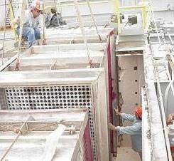
THE CHALLENGE
A manufacturer of insulation films for the electronics industry needed to evaluate their four existing oxidizers. The concern was, due to oxidizer issues, they were not following regulatory requirements. The oxidizers were manufactured by two different companies, one of which was no longer in business. The other was unable to provide an adequate response or solution. An experienced engineering company that would inspect the oxidizers and provide quality repairs for any problems that were discovered was necessary.
After evaluating the service capabilities of several equipment manufacturers and engineering consultants, they chose Anguil Environmental Systems because of their full-service solutions.
Anguil’s rigorous 75-point preventive maintenance evaluation (PME) discovered minor problems with three of the units and a major problem with the largest oxidizer, a 13,500 SCFM (21667.5 Nm³/hr) catalytic oxidizer. Anguil’s recommendations for the three smaller oxidizers greatly improved their safety and performance. Many of the suggestions from Anguil were easily implemented by the plant’s in-house maintenance staff. However, the largest oxidizer required more intensive application engineering and a comprehensive air pollution control solution.
THE SOLUTION
The larger 13,500 SCFM (21667.5 Nm³/hr) system had both a primary and secondary heat exchanger. The primary heat exchanger recovers energy from the combustion chamber exhaust and transfers it to the incoming process air stream to reduce fuel consumption. The secondary heat exchanger recovers additional energy from the primary heat exchanger outlet flow and uses this energy to preheat the air source used in the process. In this case, the secondary heat exchanger is integral to the plant’s coating process; it is used to heat the tower dryer of the AISCO coating machine. The plant engineers noticed a steady decline in the heat available from the oxidizer and secondary heat exchanger. By the time Anguil was invited in for their PME, the oxidizer took up to six hours to sufficiently heat the coater before production could begin. During the six hours of warm-up, the oxidizer had to be supplied with extra natural gas. This fuel consumption led to an operating cost of approximately $266 per startup.
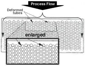 Anguil’s inspection further revealed significant damage to the heat exchanger. A third of the front tubes had separated from the bottom plenum, deforming into the second row of tubes. This effectively blocked around 25% of flow through the remainder of the exchanger. Anguil also pinpointed several areas where the airflow was bypassing the exchanger, traveling in the gaps between the exchanger and the ceramic insulation and passing through tears in the tubesheet and top plenum. The combination of bypass areas and the tubesheet tears allowed solvent vapors to circumvent the combustion chamber, greatly lowering the destruction efficiency of the oxidizer.
Anguil performed a destruction efficiency test on the oxidizer when the coated web used 100% toluene as a solvent. Under normal conditions, an oxidizer of this type should have little difficulty in attaining 98% destruction efficiency or better. Due to the airflow bypassing the combustion chamber, the oxidizer was achieving only 93.6% destruction efficiency. Not meeting the regulatory emission requirements.
Replacing the oxidizer would have radically interrupted the customer’s manufacturing schedule, resulting in capital cost increases that were unacceptable. Anguil’s solution eliminated any production disruptions by performing repairs and design enhancements over several scheduled downtimes.
THE RESULT
The first step was to replace both the primary and secondary heat exchangers. The onsite work was performed over a three-day weekend when the customer already had a planned plant shutdown.
The replacement heat exchangers significantly improved the performance of the 13,500 SCFM (21667.5 Nm³/hr) oxidizer. Previously, the oxidizer had to be run for up to six hours to meet the necessary temperature at a fuel cost estimate of $266/per startup. After the replacement, the required process air temperature is achieved in one hour. The improved efficiency results in operating cost savings of approximately $230 per startup and up to $30,000 annually. The impact of the retrofitted heat exchangers went beyond fuel savings; the improved start-up time has reduced plant downtime and increased production. They have also improved the destruction efficiency of the oxidation system and put the company in compliance.
Anguil’s analysis detailed other cost saving suggestions for the company, including:
- Ductwork adjustments for more efficient oxidizer operation
- Heat exchanger maintenance suggestions for all four oxidizers
- Review of safety controls and upgrade recommendations
- Variable Frequency Drive for the fan on the largest oxidizer to accommodate airflow changes more efficiently
- Burner maintenance suggestions
Anguil also performed airflow analysis of all processes. This information will help the company plan and budget for future growth.
The retrofitted system is currently exceeding the regulatory requirements and providing an efficient heat source for the coating lines. The Anguil service team’s expert troubleshooting and quality turnkey solution capabilities have led to another satisfied customer.
Crafting Your Oxidizer Maintenance Plan
Comments Off on Crafting Your Oxidizer Maintenance PlanOXIDIZER SERVICE SERIES: PART 2
Whether it is still on the drawing board or has been on site for years, your air pollution control system represents a significant investment and a long-term commitment to environmental compliance. A well-crafted maintenance plan for your oxidizer will allow you to get the most from your investment over the entire life of the system.
Many will come to this article hoping for a one-size-fits-all checklist for maintaining an oxidizer system. As a company that offers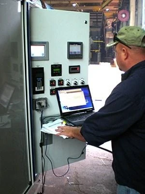 service on any oxidizer regardless of style or original manufacturer, we at Anguil have long wanted the same. A set formula for success would certainly make life easier. Absent of knowing anything else about the operating context of a particular oxidizer system, our best recommendation for a maintenance plan is as follows:
- Gather all the system documentation as listed in Part 1 of our Oxidizer Service Series. Ensure these documents are accessible to system operators and service providers.
- Stock the recommended spare parts for your oxidizer system (more on this in Part 3 of our Oxidizer Service Series)
- Establish a monthly checklist of system inspection points and make sure your operators are comfortable with what to check and how to record their findings
- Maintain an operator logbook or journal of system issues
- Obtain a yearly Preventive Maintenance Evaluation (PME) from an independent or third-party oxidizer service provider such as Anguil
- Establish remote access capability to your system’s controls from an oxidizer service provider such as Anguil
Some may choose to take this basic recommendation for a maintenance plan, stop reading here, and run with it. We would agree that anyone complying with all the steps as outlined above is indeed trying to maintain their oxidizer system. However, having an Oxidizer Service Provider like Anguil visit your site could jump-start the implementation of such a plan.
Maintenance Plan Considerations
The following influences the decision to utilize an oxidizer maintenance plan:
Production Uptime – An informed staff and a transparent maintenance plan will allow for maximum production uptime, prevent costly shutdowns, and enable a prepared response to operational irregularities.
Compliance with Environmental Regulations – The language in many air permits requires operators to stock spare parts, keep historical service documentation, and maintain the system according to the manufacturer’s recommendations. Running out of compliance parameters can not only be costly but could potentially turn into a public relations disaster.
Compliance with Safety Regulations – Compliance codes often require that safety evaluations be performed on an annual basis. Anguil incorporates these safety assessments as a part of our standard 75+ point Preventative Maintenance Evaluation.
Operating Cost Reduction – A good maintenance plan will often pay for itself by ensuring your oxidizer system is running at peak efficiency and with minimal downtime.
Maintenance Plan Elements
The right maintenance plan for one company might not be the right plan for another. Anguil considers the following to be components of a customized comprehensive maintenance plan:
- System Documentation – Gather all the documentation in one binder as outlined in Part 1 of our Oxidizer Service Series. Ensure this documentation is available to both system operators and service providers. We recommend storing relevant documents
 inside the control panel for easy access.
 - Recommended Spare Parts Package – An Oxidizer Service Provider like Anguil can identify the critical components, recommended components, and convenience items you should stock to maintain smooth operation of your system and limit production down time.
- Annual Preventive Maintenance Evaluation (PME) – Often done by an Oxidizer Service Provider like Anguil. This is not just our advice; this is rapidly becoming part of Permit Codes and Compliance – both environmental codes and safety codes. Anguil’s standard PME program includes a two-to-three-day service visit utilizing a 75+ point checklist to ensure your oxidizer meets air pollution control standards. After, results are sent by formal report for your maintenance records.
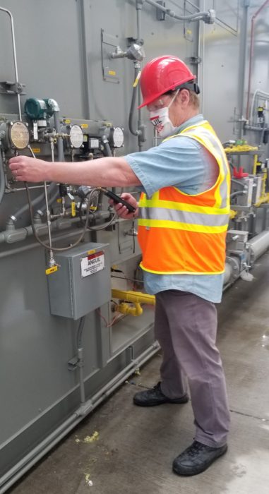 inside the control panel for easy access.
The next four options can be performed in conjunction with a PME visit or separately as stand-alone services.
- Destruction Removal Efficiency (DRE) Evaluations – An oxidizer service provider like Anguil can check the VOC destruction efficiency of your system on site with portable testing equipment or via laboratory analysis of air samples. This service keeps you on track with system performance and verifies compliance. It is ideal as a pre-test to help eliminate “surprises” during expensive formal compliance testing.
- Repeat Operator Training – Maintenance personnel take pride in servicing the equipment when they are familiar with the operation. Years one and two of an oxidizer’s life can present different maintenance challenges than years three and beyond. Repeat training keeps operating personnel prepared to meet evolving service needs. Repeat Operator Training is also becoming a requirement in NFPA codes.
- Catalyst Services – At the heart of every Catalytic Oxidizer System is the catalyst bed. When properly maintained, the catalyst bed can provide years of high VOC destruction at temperatures well under those required for thermal oxidation. Anguil offers a full program of catalyst services including evaluation, testing, rejuvenation, replacement, and the purchase back of “spent” catalyst for recycling.
- Split Preventative Maintenance Evaluations – Some facilities have minimal downtime available for system repairs but still want to be prepared with the right parts and contractors when their downtime occurs. They may elect a Split-PME scenario, which starts with a one-day system evaluation visit by a Field Service Engineer. A second visit is scheduled for the Field Service Engineer to return with parts and materials identified previously, prepared to execute the recommendations immediately.
Other areas to consider in maintaining support of your oxidizer include semi-annual Preventive Maintenance Evaluations (PMEs), remote login capability, operating cost reviews, maintaining an operator log book, weekly/monthly inspections, as well as multi-year and multi-facility maintenance programs.
- Semi-Annual Preventative Maintenance Evaluations – For some, a once-yearly comprehensive Preventive Maintenance Evaluation is not enough. Overall system balancing, operational cost verification, and inventory of spare parts should be conducted semi-annually instead. Depending on the complexity of your system, you may wish to contact Anguil to perform this service for you.
- Remote Login Capability – Establishing remote login access is one of the most important things you can do when creating your maintenance plan. Remote Access Capability has recently become a game changer in the oxidizer service world. For the companies and oxidizer systems we service, when the capability is in place, it is both a lifeline during system upsets as well as a “force-multiplier” when our Field Service Engineers are on site. It is akin to getting the experience and knowledge of several engineers on site, for the price of one. Adding this service quarterly is becoming a popular option. In today’s world, no oxidizer end-user should be left without this critical safety net in place. Don’t wait for an emergency to find out the connection isn’t there. For those with this feature, make sure to regularly test your connection.
- Operating Cost Review – Do you know exactly how much your system should cost to run? Are you getting the most for your operating dollars? Anguil offers an Operating Cost Review Program that can answer these questions and provide cost-saving recommendations tailored for your oxidizer system.
- Operator Logbook – Thorough service history documentation, including a record of daily, weekly, and annual inspections, is often a requirement for an air permit. A comprehensive operator log will help diagnose operating irregularities and could prevent costly malfunctions down the road.
- Weekly Walk-By Inspections – Typically performed by your own workforce. An Oxidizer Service Provider like Anguil can custom design weekly inspection checklists for your specific oxidizer system.
- Deeper Monthly/Maintenance Day Inspection Checklists – For our Monthly Inspections program, we provide a list of the system components needing inspection, independent verification, or calibration. Our goal is to train your maintenance team to feel comfortable performing the monthly checks on their own.
- Custom Maintenance Plans (Multi-Year and Multi-Facility Packages) – Developing a maintenance plan with an Oxidizer Service Provider builds a strong service relationship built on trust and long-term oxidizer expertise. Anguil’s custom maintenance plans include multi-year deals for individual plants or for multiple facilities. Custom multi-year and multi-facility maintenance plans can offer numerous benefits.
Routine Maintenance Benefits
- Smooth Equipment Turnover Between Project Engineering and Production Engineering Teams – Many oxidizer systems are purchased via a project engineering team who then turns the equipment over to production teams. This hand-off can proceed more smoothly if the production team sees there is a service agreement already in place.
- Reliable Budgeting – Having a multi-year service plan takes guesswork out of operational budgeting.
- Consistent Service History – By having a service history log, despite retirements or other turnover in the workforce, the service schedule remains consistent.
- Knowledge Sharing – Maintaining service history at the plant level can be difficult enough. A corporate level maintenance plan can be a conduit for improved knowledge sharing between plants.
- Uphold Corporate Values – Environmental Compliance is often part of a Corporate Level Mission Statement.
Reliability Centered Maintenance
Anguil participated in a three-week-long Reliability Centered Maintenance (RCM) evaluation of an oxidizer system. This system treats the exhaust from a critical production line in one of the most highly regulated areas of the country. RCM is a landmark maintenance concept defined in John Moubray’s book Reliability-Centered Maintenance as “a process used to determine the maintenance requirements of any physical asset in its operating context.”
A team of Anguil personnel, along with the facility’s maintenance team, equipment operators, electrical controls specialists, and EHS staff were guided by an RCM facilitator. The team went line-by-line through the oxidizer electrical schematics, sequence of operation, control programs, and environmental permit requirements to define the system’s functions and possible failures. Using the framework of the RCM program, the team generated lists of potential redesigns, required procedures, a compulsory spare parts program, and implementation reports for the system. This was no small task — the final report was over 400 pages long! The evaluation was a significant investment in money and manpower for both Anguil and the company involved.
The biggest takeaways from this experience were:
- This is the level of training operators of oxidizer systems deserve but rarely receive.
- The importance of “Operating Context” in determining a suitable approach to the long term maintenance of an oxidizer system.
To further illustrate the idea of operating context, consider that oxidizers today are being installed into production scenarios where they:
- May be allowed to be offline for several weeks or months each year.
- May force the end-user to stop all production immediately when offline, in some cases triggering “Notices of Violation” and fines upon any upset condition.
- May be treating exhaust gas streams that are immediately dangerous to life and health.
- May be the sole source of heat for the process to which they are attached.
Each one of these different operating contexts plays a major role in the final determination of a maintenance plan for an oxidizer system.
Not everyone can afford a formal RCM maintenance program for their oxidizer system. There are also industries with enough acquired experience where such an effort may not be required. However, an effective and custom maintenance plan adhering to minimum requirements can be crafted with help from an Oxidizer Service Company like Anguil. A customized program will prolong the life of the equipment while staying within the parameter of an operating budget.
There is no one-size-fits-all solution for crafting a quality oxidizer safety and maintenance program. At Anguil, we strive to offer a wide range of services to make crafting even a basic maintenance plan an essential and affordable investment. Our experienced service personnel look forward to assisting in designing the smartest maintenance program for your company.
This is the second of four parts in Anguil’s Oxidizer Service Series. We encourage you to also view Part 1: Better Maintenance Starts With Better Documentation as well as Part 3: Stocking Spare Parts for Your Oxidizer System and Part 4: Oxidizer System Optimization.
From EPA Penalties to Peak Performance: Anguil’s Catalyst Replacement Success Story
Comments Off on From EPA Penalties to Peak Performance: Anguil’s Catalyst Replacement Success Story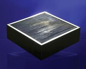
THE CHALLENGE
Imagine investing in an expensive system to treat your manufacturing exhaust for pollutants, and instead of treating the air you face complaints from neighbors, a supplier that can’t find or repair the problem, a large environmental fine, and financial penalties compounding daily. Certainly, it seems overwhelming at the least. Unfortunately, a New Jersey pharmaceutical company found themselves in that exact situation after purchasing a thermal incinerator to treat the heptane and hexane in their exhaust.
The thermal incinerator’s “tubular” design was modified with a catalyst bed to reduce the system’s operational costs. Alas, when operating in catalytic mode, the oxidizer failed to provide the 95% destruction efficiency of non-methane hydrocarbons required by the New Jersey Department of Environmental Protection. These odorous emissions led to an environmental protection agency (EPA) consent decree, complete with a $175,000 civil penalty. Although the company was proactive in trying to solve the emission problem, the EPA assigned penalties of $2,500 for every day the violation persisted. The original equipment supplier attempted to rectify the issue but were unable to identify the problem. Leaving the pharmaceutical company in violation of their New Jersey air permit and racking up more fines every day.
THE SOLUTION
After struggling, and ultimately failing, to solve the problem with the original supplier, the pharmaceutical company reached out to Anguil Environmental Systems, Inc. Anguil’s proven expertise with catalytic systems, deep knowledge of catalyst science, and engineering abilities made us the candidate best suited to tackle the volatile organic compound (VOC) problem successfully.
The first step in Anguil’s approach was to explore the reason for catalyst nonperformance. There were several potential reasons for catalyst failure. The possibility of catalyst masking or the presence of a poisoning agent (i.e. sulfur, phosphorus, heavy metals) within the VOC-laden stream was examined. However, no significant levels of any of these agents were detected.
Another possible reason was the industrial process stream being allowed to pass through the oxidizer before it was brought to proper operating temperature. This would result in coating the stainless-steel rings with the heptane and hexane hydrocarbons. If this was the case, when the unit was brought to the proper operating temperature, oxidation would occur on the catalyst, leaving a carbon deposit. This type of carbon deposit would result in the formation of incomplete combustion products and decreased destruction efficiency. No signs of these carbon deposits were detected.
Having eliminated the initial possibilities, Anguil conducted a laboratory performance test that finally indicated the true reason for catalyst failure: the catalytic stainless-steel rings lacked the proper surface area to achieve the promised destruction efficiency. This insight revealed there was less than 50% destruction efficiency of a test stream, indicating a catalyst failure.
THE RESULT
Anguil’s remedy was a honeycomb catalyst. The catalyst has a 300 cell-per-square-inch ceramic substrate. This focused design is more than 100 times the surface area than the old stainless-steel rings – a single cubic foot offers more surface area than an entire football field! This significantly increased the catalyst’s efficiency and reactivity. The oxidizer was equipped with a new reactor section to house the nine cubic feet of monolithic catalyst. A 95% destruction efficiency guarantee was provided along with the system retrofit.
A follow-up flame ionization detector (FID) was also performed on this retrofit and a carbon filter was added to eliminate methane readings. The FID test results indicated a VOC inlet concentration of 943 ppm and an oxidizer outlet concentration of less than 20 ppm. The company is now EPA-compliant with a 97.8% destruction efficiency.
This case study underscores Anguil’s commitment to delivering not just equipment, but comprehensive solutions that ensure environmental compliance and operational peace of mind.
Better Maintenance Starts with Better Documentation
Comments Off on Better Maintenance Starts with Better DocumentationOXIDIZER SERVICE SERIES: PART 1
Part of properly servicing your oxidizer system is maintaining the design documentation associated with that system. When it comes to oxidizer design, National Fire Protection Association (NFPA) standards are considered good practice.
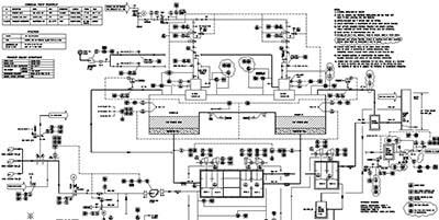
The following are critical design documents oxidizer users should save that contain information required by the NFPA to implement an overall system reliability plan. Anguil uses the same documents to offer value-added service, regardless of the original manufacturer.
- Process and Instrumentation Diagram (P&ID): The P&ID is the command drawing that summarizes instrumentation, safety devices, operational limits, and control loops. The P&ID typically provides the oxidizer component tag numbers, as well as the number, and type, of process exhaust pick-ups for the system. The system utility requirements and performance parameters may be listed as well.
- Electrical Schematics: Electrical schematics provide detailed connectivity of the system and are an important tool used for troubleshooting. It is critical the electrical schematics are not only readily available but also revised to stay current with system changes.
- Sequence of Operation / List of Set Points & Alarm Conditions: The sequence of operation is a step-by-step description of how the oxidizer is designed to operate. This includes how the unit starts, how the process exhaust is brought on-line, how airflow and temperature control are maintained, and how the unit safely shuts down. Set points and alarm conditions of the system are also included in this document. It is important to note that this documentation is required per the National Fire Protection Association’s NFPA 86: “Wiring diagrams and sequence of operations for all safety controls shall be provided” (From NFPA 86: Standard for Ovens and Furnaces, 2019 Edition – Section 4.1.1.2).
- Programmable Logic Controller (PLC) Program: If your system requires a PLC, we recommend keeping a fully documented copy of the PLC program for your records. Some oxidizer suppliers may be reluctant to release this information to system end-users because PLC programs can include proprietary control schemes. However, with a signed confidentiality agreement in place, end users should be able to obtain this code. If your oxidizer manufacturer is no longer in business, it is possible to upload the program directly from the PLC. If this is the case, the program may be undocumented, and you may need an oxidizer service provider to re-enter the code documentation. Information on Anguil’s PLC programming capabilities can be found here.
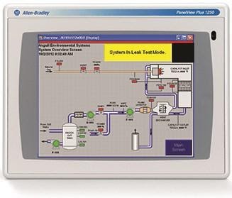
- Human Machine Interface (HMI) Program: The HMI (Operator Interface / Operator Touch Screen) is the operator’s window into the workings of the oxidizer’s PLC. The HMI program connects with the PLC program to control your oxidizer system by displaying data points from the PLC along with set points and tuning parameters. An operator can adjust the set points and tuning parameters from the HMI. The HMI provides system status or alarm messages based on the PLCs outputs. In the event the display fails, you should be prepared to download your HMI program to a replacement display from your spare parts inventory.
- Expected Pressure-Temperature Profile: It is critical to know your pressure point values to set up a regular inspection plan for your maintenance personnel. Ideally, you should have a table showing expected pressure and temperature data at the common process exhaust airflow amounts your production requires. If this is unknown, ask your system provider to provide data for two conditions: at full-oxidizer airflow capacity and at half-oxidizer airflow capacity. Using this data, you can approximate the points between when establishing your customized inspection checklists.
- Permit Compliance Documents: Compliance documentation requirements vary across local, state, and federal agencies, making it difficult to provide a generalized recommendation. Anguil recommends organizing your permit compliance documentation in a single document that includes minimum temperatures, operating temperatures, and bypass limitations. This document will keep all parties aware of the key compliance parameters to monitor and record with respect to your oxidizer system.
- Bill of Materials / Recommended Spare Parts Lists: A complete bill of materials will allow you to know the replaceable parts needed to maintain system operation. Ideally, the parts listed in the Bill of Materials would be further categorized as “Critical Spare Parts,” “Recommended Spare Parts,” “Consumable Spare Parts,” “Convenience Items,” “Long Lead Time Components,” etc. This enables operators to decide on the type and quantity of spare parts to stock based on specific production and compliance requirements. Some air permits require critical spare parts to be kept on hand. More detailed information on these categories can be found on the Spare Parts section of our website.
Here are some additional highlights regarding system documentation from the current edition of NFPA 86 Standard for Ovens and Furnaces 2019 Edition:
- 4.1.1.1 Plans shall be drawn that show all essential details with regard to location, construction, ventilation, piping, and electrical safety equipment. A list of all combustion, control, and safety equipment giving manufacturer and type number shall be included.
- 4.1.1.2 Wiring diagrams and sequence of operations for all safety controls shall be included.
- 7.3.3 Operating instructions that include all of the following shall be provided:
- (1) Schematic piping / wiring diagrams
- (2) Startup procedures
- (3) Shutdown procedures
- (4) Emergency procedures
- (5) Maintenance procedures
- 7.3.4 When the original equipment manufacturer no longer exists, the user shall develop inspection, testing, and maintenance procedures.
This is the first of four parts in Anguil’s Oxidizer Service Series. We encourage you to also view Part 2: Crafting Your Oxidizer Maintenance Plan as well as Part 3: Stocking Spare Parts for Your Oxidizer System and Part 4: Oxidizer System Optimization.
From Emergency to Efficiency: Rapid Media Replacement for High-Volume RTOs
Comments Off on From Emergency to Efficiency: Rapid Media Replacement for High-Volume RTOs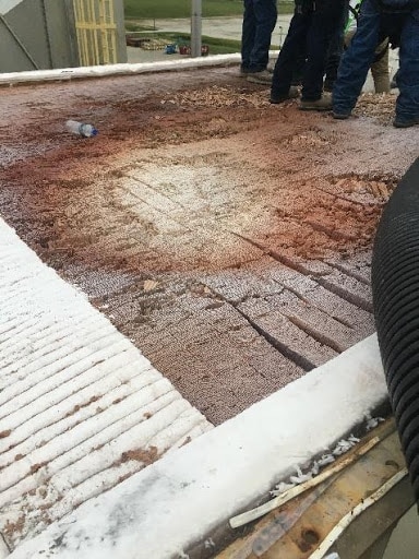
THE CHALLENGE
Media replacement is a routine process needed for the maintenance and performance of oxidizer systems. Media replacement is most performed on a regenerative thermal oxidizer (RTO) when the media becomes plugged from contamination in the process stream fed to the RTO. Anguil Environmental Systems frequently replace media in not only Anguil manufactured systems, but also in non-Anguil manufactured systems.
Unfortunately, many manufacturers do not keep up with their routine maintenance or even have a preventative maintenance plan in place. By the time they realize the media needs replacement, it is an emergent situation and results in system downtime. A compounding factor is a potentially unresponsive OEM provider.
This was just the situation a worldwide automobile supplier found themselves in with two of their systems. Dissatisfied with their OEM’s lack of response and needing immediate assistance to avoid a costly shut down, they reached out to Anguil Environmental Systems in search of a solution.
THE SOLUTION
While the Megtec CleanSwitch systems were installed at two different plant locations in the United States, they were both 65,000 SCFM (104,325 Nm³/hr) units. Anguil offered a site visit as soon as possible, which included an investigation of what the root cause was. In this situation, the Anguil representative found plugging and flame impingement to be the issues. During the visit, the original design of the media bed was mapped. With that information a new media bed was designed that would resist plugging while maintaining performance.
THE RESULT
One of the RTOs was located on a three-story roof, and a considerable distance away from the exterior wall. This posed a complication to the repair work and required more planning and materials. Instead of the normal procedure, the upper half of the RTO had to be removed, and a high lift crane was needed to accommodate the heights and distances.
The second RTO was crucial to their manufacturing process, and the company couldn’t afford to have an extended shutdown. To accommodate the requirement Anguil’s crew not only performed the work over a weekend, during normal shutdown hours, but worked double shifts so production was not affected.
Anguil completed both projects early, and under budget, due to extensive preparation and clear communication with the customer. Thanks to our exceptional performance in this emergent situation, the customer has continued to rely on Anguil for their other units and plants.
Rubber Curing Emissions
Comments Off on Rubber Curing EmissionsThe Challenge
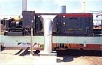 A rubber vulcanization company was looking for a new, affordable abatement solution to treat their blue haze and low-level Volatile Organic Compounds (VOCs) in order to meet regulatory requirements. The large Electrostatic Precipitator (ESP) in use was extremely expensive to operate and maintain. The company began their search for a system that offered effective opacity control and could also reduce operating costs. The air pollution control supplier would need the ability to engineer the optimum solution and have the product breadth necessary to apply the correct technology.
The Solution
After thorough technical evaluation, the plant selected Anguil Environmental to solve their VOC emission problem and put them in compliance. Anguil installed its patented Self-Cleaning Ceramic Filter (SCCF) to eliminate the blue haze and the VOCs.
 The Result
 The Result
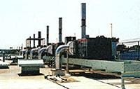
In order to alleviate the maintenance headaches of their ESP, the owner inquired about a thermal oxidizer. However, the fuel costs of a thermal system are almost equal to the maintenance cost of an ESP for this application. Because of its fuel efficiency and lower operating costs, the Regenerative Thermal Oxidizer (RTO) was a possible option but Anguil found that the footprint and the weight of the unit could not provide the flexibility the customer desired. Anguil’s engineers concluded that an SCCF was the most effective solution.
One of the major considerations in designing a treatment system for a rubber curing process is that the ducts must be kept clean from any particulate buildup. Large treatment systems, like an ESP or RTO, also involve long duct runs. This combination makes many treatment solutions both costly and dangerous, since particulate buildup can cause duct fires.
Anguil worked with the customer and their process engineers to design a solution that greatly reduced duct maintenance cost and provided effective opacity and VOC control. The small footprint of multiple SCCFs allowed Anguil to roof-mount the units and treat 1,500 SCFM (2,407.5 Nm3/hr) over each of the oven “zones” with direct duct runs. By making shorter and more direct duct runs, Anguil engineers reduced the risk and associated costs of particulate buildup.
Added benefits of the Anguil SCCF include a 40% effective shell and tube heat exchanger, providing even greater cost savings through heat recovery. Anguil’s flexibility also provides options for future adjustments in pollution control. Because the plant was located in an area that may come under more stringent environmental regulations, Anguil’s SCCF can be equipped with catalyst to achieve greater than 95% VOC destruction.
After a successful SCCF pilot, Anguil’s engineers worked with the customer to provide the most effective and lowest-cost operating system. Flexibility, experience and constant pursuit of better design resulted in another satisfied Anguil customer.
World’s Largest Remediation Site: Stepping into a Second Phase of Utilization with 21st Century Technology
Comments Off on World’s Largest Remediation Site: Stepping into a Second Phase of Utilization with 21st Century Technology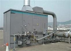
THE CHALLENGE
Once the world’s busiest airport, Hong Kong’s Kai Tak Airport closed its runways in 1998. When the airport was decommissioned, the government planned to rapidly clean the site for commercial and residential development. After decades of various fuels and chemicals leeching into the soil, the site required an extensive and sophisticated groundwater cleanup. A system that could destroy a minimum of 95% of the volatile organic compounds (VOCs) and minimize operating costs was necessary. Since the project generated intense government interest, and was highly publicized, the chosen treatment system had to be both proven and reliable.
After an extensive evaluation of various VOC treatment solutions, the consultant selected a system from Global Technologies, the remediation division of Anguil Environmental. With their extensive engineering support, industry-leading reliability, and history of solving difficult remediation problems around the world, Global was the clear choice. Global engineers performed a careful evaluation of the data and recommended a Model 80 Remedi-Cat ™ forced draft system. The system processes 8,000 SCFM (12,616 Nm³/hr) of VOC-laden air and provides at least 95% destruction rate efficiency.
Global Technologies’ experience with processing large air flows and irregular organic loading was crucial to this project. The proven performance of Global treatment systems provided the Kai Tak project engineers the confidence to design an innovative remediation plan. Global Technologies’ vapor treatment system was at the heart of this strategy.
THE SOLUTION
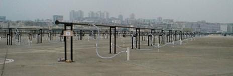
Taking an aggressive approach to remove the subsurface contaminants, the engineers installed 2,000 soil vapor extraction (SVE) wells and 1,000 sparge wells across the old airport tarmac. The vast airflow was directed from the wells to a single treatment system. This strategy provided significant savings in energy, fuel, and personnel compared to a modular approach. A modular solution would require more treatment systems to treat a limited number of wells.
Global chose a catalyst that utilizes honeycomb shape construction to provide superior airflow and low pressure drop. The catalyst selected had undergone extensive technical development, and field-testing, and was chosen to accommodate the unique airflow volume, the amount and type of VOC, and the desired destruction efficiency of the project.
Another key design feature of Global Technologies’ vapor treatment system was the variable frequency drive (VFD). The VFD controls the speed of the system fan, regulating airflow through the system and allowing the oxidizer to efficiently handle the air volume fluctuations from the 2,000-plus extraction wells. With a maximum turndown ratio of 10:1, the VFD produces energy savings far superior to an inlet vane damper. Global provided the VFD with a particulate filter and housed it in a NEMA 4 enclosure to protect it from the sun and outdoor elements.
Like all Global Technologies’ systems, the Model 80 Remedi-Cat™ was manufactured with the highest quality workmanship and construction materials. The heat exchanger and reactor were constructed of 304L stainless steel with continuous leak-tested welding around all seams. To withstand the natural elements, the exterior shell was constructed of aluminized steel with a coat of UV resistant polyurethane paint. High-density mineral wool was placed between the inner and outer shells to maintain external skin temperatures at safe levels.
THE RESULT
A final consideration was worker and equipment safety, which is a significant concern for every Global Technologies system, but is especially important on a high-profile project like Kai Tak. With safety in mind, Global developed a state-of-the-art Programmable Logic Controller (PLC) which allows safe and intelligent operation with minimal risk. The PLC provides immediate troubleshooting, first-out shutdown detection, and operator assistance for start-up. Global Technologies’ user-friendly features provide the on-site operators with more control, decreased downtime, and reduced maintenance costs.
Global Technologies’ understanding of a customer’s unique needs, coupled with the engineering know-how necessary to fulfill these needs, resulted in another satisfied customer. The cost-saving strategy of controlling numerous wells with one treatment system was made possible by Global Technologies’ ability to accommodate the large and varied airflow from the wells. Global Technologies’ aggressive and innovative treatment strategies assisted the once busiest airport move into a cleaner and safer 21st century.
Pemaco Superfund Site Remediation
Comments Off on Pemaco Superfund Site Remediation The Challenge
 The Challenge
Pemaco was formerly a chemical facility located in a light industrial and residential area of Maywood, CA, adjacent to the Los Angeles River. No one knows how long hazardous substances had been leaking into the ground but the operations date back to the 1940’s. Up until closure of the facility in 1991, chlorinated solvents, aromatic solvents, and flammable liquids had all been used in the chemical mixing, blending, storage and distribution processes at this location.
After a fire at the abandoned Pemaco location, the Environmental Protection Agency (EPA) was called in to stabilize the site and conduct an emergency assessment to determine the extent of contamination into the soil and groundwater.
The EPA worked with several environmental consultants to define a detailed remediation plan for the superfund site. It was determined that solvents and other compounds from tanks and drums caused soil contamination deeper than 90 feet. A 14-acre groundwater plume that migrated into a complex aquifer system under residential properties threatened local water supply wells with Perchloroethylene (PCE), Trichloroethylene (TCE), Trichloroethane (TCA), Dichloroethane (DCA) and Vinyl Chloride (VC).
The Solution
The remediation technologies used would include Electrical Resistance Heating (ERH), Soil Vapor Extraction (SVE), thermal oxidation, acid gas scrubbing and carbon absorption. The goal was to completely remediate the 1.4-acre site of these Volatile Organic Compounds (VOCs) and redevelop it as a public park. The vapor treatment portion of the project combined ceramic core flameless thermal oxidation (FTO) with acid gas scrubbing, vapor conditioning, and a carbon adsorption polishing step to control potential dioxin emissions.
 The Result
 The Result
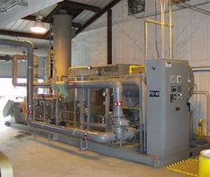
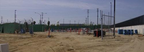
Working with several environmental engineering firms and the US Army Corp of Engineers, Global Technologies supplied a 1,000 SCFM (1,605 Nm3/hr) Flameless Direct Fired Thermal Oxidizer (DFTO) with a caustic scrubber for emission treatment from the SVE units. The vapor treatment system was designed to handle typical averages of 315 parts per million (ppm) but capable of maximum spikes up to 25,000 ppm.
The oxidizer was designed to achieve 99.9% destruction of hydrocarbons with a unique gas-fired burner that generates virtually no nitrogen compounds (NOX) during combustion. The patented surface combustion technology ensures that all emissions are exposed to the high temperature zone only along the innermost surface. Another important advantage of this arrangement is that hot combustion gases are completely contained within the burner and the oxidizer outer shell remains cool. Therefore the flameless oxidizer can be processing toxins in a matter of seconds after ignition.
A gas flow control valve was integrated to reduce operating costs. By reducing gas flow as the energy content of the VOCs increases the oxidizer uses less supplemental fuel for combustion. It operates in response to control signals from a thermocouple located immediately downstream of the oxidizer burner.
Downstream of the oxidizer, exhaust gases flow into the integral scrubber quench chamber via Fiberglass Reinforced Polymer (FRP) ducting. Adjacent to the oxidizer, the skid mounted scrubber uses polypropylene packing to treat the acid gases. It was optimized to reduce the water usage without sacrificing spray coverage and the design allowed for a max HCl loading of 472 lbs/hr.
The flameless DFTO and scrubber were arranged in an induced draft configuration, pulling exhaust through the system and keeping it under negative pressure to prevent the escape of any corrosive gases.
The United States EPA filmed a documentary about the Pemaco remedial action for internal training purposes. The documentary highlights several “firsts” for the EPA including the use of a flameless thermal oxidizer for vapor treatment. More information can be found on the EPA website.
Balancing Low Fuel Consumption and High Destruction Efficiency at Remote Remediation Sites
Comments Off on Balancing Low Fuel Consumption and High Destruction Efficiency at Remote Remediation SitesTHE CHALLENGE
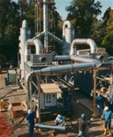
A large consulting and contracting firm owns and operates several ex-situ Thermal Desorption Units (TDUs) approved for use under the Resource Conservation and Recovery Act (RCRA); the Comprehensive Environmental Response, Compensation and Liability Act (CERCLA); as well as for use at private industrial remediation sites containing a wide variety of chlorinated and non-chlorinated contaminants up to concentrations of 3,000 ppmv. Being mobile, the TDUs can be deployed anywhere in the country and would be subject to varying local environmental regulations on hydrogen chloride (HCl) emissions produced from the thermal oxidation of halogenated compounds. Lastly, the operating cost of the full remediation solution directly affects the total project cost and ultimately the firm’s bottom line. To meet their technical and commercial project requirements, the customer was seeking an Air Pollution Control solution capable of handling a wide range of contaminants and mitigating HCl emissions all while being easily mobilized and possessing the lowest operational cost possible.
After a thorough technical evaluation and bid process, the customer selected a complete, mobile treatment package from Anguil Environmental Systems’ Wastewater Treatment team (FKA Global Technologies), containing a Chlorinated Catalytic Oxidizer (Chloro-Cat) and acid gas scrubber package. Anguil’s solution was selected due to our experience with over 30 such systems already installed to treat similar chlorinated streams from Soil Vapor Extraction sites as well as groundwater remediation sites utilizing air strippers.
THE SOLUTION
 A catalytic solution was selected largely due to the oxidizer’s compact body and ability to operate at lower combustion temperatures, making it mobile and cost effective to run as compared to a traditional Direct Fired Thermal Oxidizer. The lack of inexpensive natural gas feeds at many remediation sites dictates the use of propane for supplemental fuel and because direct thermal oxidation requires operating at temperatures between 1600°F – 2000°F considerable amounts of costly propane would be consumed over the course of the project. By contrast, each TDU could be expected to exhaust up to 5,000 SCFM of desorption air at temperatures between 400°F – 900°F which is at or near the minimum inlet catalyst temperature. Because the incoming process temp was already preheated by the TDU little supplemental fuel would be required by the Chloro-Cat. As with all Anguil chlorinated catalytic systems, a 316L stainless steel shell and tube heat exchanger would be installed in the 316L stainless steel reactor to further minimize propane consumption.
To mitigate HCl emissions, Anguil utilized a high temperature quench on the Choro-Cat exhaust followed by an acid gas scrubber constructed of Fiberglass Reinforced Plastic (FRP). HCl is removed from the air stream by interaction with either a recirculating caustic solution or using once through water. An induced draft FRP fan on the back end of the treatment package was provided to pull vapors through the system due to the high temperature, highly saturated exhaust from the TDU and the resultant HCl acid gasses.
As this was a soil heating application, utilization of a high-temperature baghouse dust collector on the TDU skid removed concerns associated with dust or dirt plugging of the monolithic catalyst cells.
Anguil was able to package the entire system onto a 50′ drop deck trailer. In addition to the Chloro-Cat and scrubber, the trailer included a Liquid Propane Vaporizer and a storage area for equipment transport.
THE RESULT
Anguil’s experience proved invaluable in designing and implementing the proper solution for this application. The chlorinated catalytic system was designed to provide 99% destruction efficiency at operating temperatures of 500°F – 850°F to reduce auxiliary fuel usage and meet the customers’ needs for performance and low OPEX. Safety systems were installed to ensure no HCl condensation to minimize equipment corrosion to protect the customer’s investment, and with the modular trailer mounted solution, eased the customer’s ability to deploy to multiple sites. The most recent compliance testing of this turnkey package demonstrated over 99% destruction of all compounds.