


Air-to-Water Heat Exchanger Reduces Operating Costs by $120,000 per year
Comments Off on Air-to-Water Heat Exchanger Reduces Operating Costs by $120,000 per year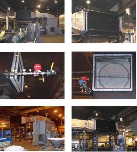
THE CHALLENGE
When designing an oxidizer, local and federal requirements are taken seriously into consideration. Each system is customized for the location it will be run at. Sometimes, a unit must be moved to a different location. It may have been purchased by a different company, or the owner may be moving to a new location. No matter the reason for the move, the system will need to be reassessed and modified to ensure compliance with regulations at the new location.
When a leading pharmaceutical manufacturer needed to relocate an oxidizer across the United States, they turned to the expertise of Anguil Environmental Systems. The company’s 5,000 SCFM (8,025 Nm³/hr) oxidizer needed to be evaluated and updated to achieve the performance expectations at the new facility, which were different from the regulations at the original location.
THE SOLUTION
Anguil began by conducting a detailed review of the system. A field service engineer went on site to inspect the oxidizer. A report detailing the condition of the oxidizer at its current location was generated, as well as a written procedure for the proper disassembly and reassembly of the equipment. The service engineer made recommendations outlining the modifications necessary to make the unit run at the new facility’s required energy, and destruction efficiency rate.
THE RESULT
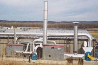
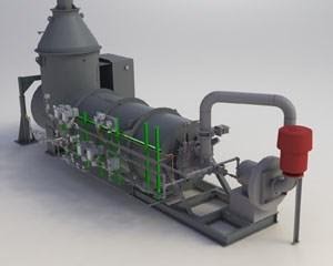
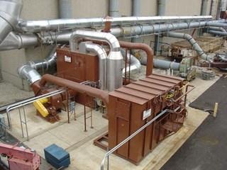
With the review complete, Anguil worked closely with the customer to update the system. The modifications included a control package upgrade and a new hot gas bypass damper. To address the energy recovery requirements at the new facility, an economizer was installed between the oxidizer and exhaust stack to transfer heat to water. The exhaust heat from the stack was transferred to the Anguil economizer which created hot water. This otherwise lost energy was captured and used in various applications such as boiler feedwater, cold makeup water, processed water, glycol, and thermal fluids.
The stainless-steel system tube and fin style heat exchanger has access doors for inspecting and cleaning the tubes. The exhaust flow from the catalytic oxidizer is 5,400 SCFM (8,667 Nm³/hr) and the temperature is 450°F (232°C). Roughly 160 GPM of water is heated to 140°F (60°C) with the economizer. The total energy recovered was 1.43 MM BTU/hr or an estimated total savings of $120,512 per year. The upgrades not only optimized performance but also delivered substantial energy savings to help the customer meet both their operational and sustainability goals.
A Competitive Advantage in Semiconductor Fabrication
Comments Off on A Competitive Advantage in Semiconductor FabricationTHE CHALLENGE
In the face of rapid industry advancement, semiconductor chip manufacturers are continually looking for an edge in the competition. In the past that required the manufacturers to stay current with the latest trend in wafer sizes. A new option is through innovative pollution control technologies and changing techniques in their production plants.
At Anguil, our customers know they can trust our team to develop and deliver quality solutions to their unique environmental and process challenges. We are experts in environmental efficiency through custom design and manufacturing of air pollution, water treatment, and energy recovery systems.
In one case, a large semiconductor chip fabricator wanted to reduce their environmental impact, maintain their productivity, save on operational costs, and conserve valuable floor space.
 The process of fabricating semiconductor chips generates significant amounts of wastewater and waste gases, both of which require treatment prior to their release into the sewer system or atmosphere. As fabrication operations have increased, so too has the amount of waste produced and, consequently, the need for abatement technology.
The customer approached our team with a request for a new system for their plants. They wanted to stay ahead of their competition by tackling the challenge of reducing their environmental impact without sacrificing their facilities’ productivity and output. While they were currently employing the use of two systems, each with capacities for less than 50,000 SCFM (80,250 Nm3/hr), they were looking for a more effective solution. Ultimately, they were seeking a system that doubled their SCFM volume processing capacity with a 98% VOC removal level.
Their exact system requirements were as follows:
- >100,000 SCFM (160,500 Nm3/hr) volume processing capacity in a single system with the same footprint as the two existing pollution control devices
- >98% VOC removal efficiency
- No upstream pressure fluctuations
THE SOLUTION
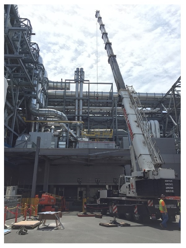
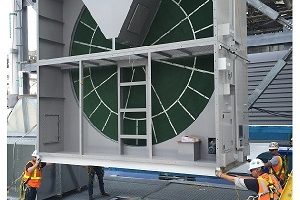
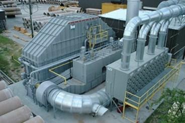
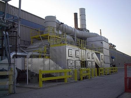
After reviewing the customer’s requirements and discussing the project objectives, our team decided that rotor concentrator thermal oxidizers (RCTO) would be the ideal air pollution control solution. The units were designed with a zeolite rotor concentrator wheel sized to handle more than 100,000 SCFM (160,500 Nm3/hr) of process air, a custom-designed thermal recuperative oxidizer (TO) with a DRE of >99.5%, and a specialized heat exchanger to minimize silica build-up and facilitate maintenance operations.
Once fully assembled, all three systems were installed on mezzanine levels of the existing plants. After installation, our technicians completed final commissioning and provided comprehensive operator training. Ultimately, the customer was left with a system that met their needs and a team trained to properly use that equipment.

THE RESULT
Each system was able to exceed the processing capacity and destruction efficiency requested. The new processing capacity is double that of the two previous systems combined.
Additionally, by replacing their old air pollution systems with our more efficient system, the customer was able to save on floor space and operational costs. At the end of the project, the customer was fully satisfied with the performance of all three systems.
Learn more about Anguil’s pollution control solutions in this industry.
Wind Turbine Manufacturer Implements Clean Air Initiative
Comments Off on Wind Turbine Manufacturer Implements Clean Air Initiative The Challenge
 The Challenge
When you think about generating electricity from wind, clean energy comes to mind. However, the wind turbine production process can be a major source of air pollution without the proper controls in place. Manufacturing and painting the blades, towers, and nacelles requires composite construction material and solvent-based coatings. The potential to emit Volatile Organic Compounds (VOCs) and Hazardous Air Pollutants (HAPs) such as xylene, ethyl benzene, styrene, and phenol into the atmosphere is a major concern for communities and regulatory agencies.
The Solution
One of the world’s largest turbine manufacturers is doing their part to keep wind power a truly clean source of energy. With the expansion of several new production lines, the company enlisted help from Anguil Environmental Systems to ensure proper air pollution control from their component painting processes in The United States.
 The Result
 The Result
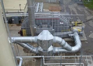
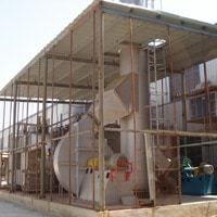
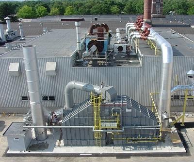
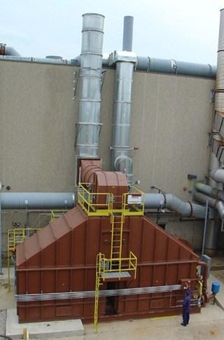
Approximately 40,000 SCFM (64,200 Nm3/hr) of solvent-laden air is diverted from multiple paint booths to an Anguil Regenerative Thermal Oxidizer (RTO), which destroys over 99% of the air pollutants. Similar to the RTO shown here, this system incorporates pre-filters to stop overspray from plugging the oxidizer ceramic media. Designed for 95% thermal efficiency, the Anguil RTO can self-sustain at low concentration levels, which reduces the need for auxiliary fuel.
Demand for renewable energy is on the rise, and experts predict that 70 to 80 new wind turbine blade factories could come online throughout the world in the next decade. With multiple systems on applications such as this, Anguil’s experience makes them the preferred vendor for emission control systems in the wind turbine market.
Styrene Emissions: Catalytic Oxidizer with Concentrator
Comments Off on Styrene Emissions: Catalytic Oxidizer with Concentrator The Challenge
 The Challenge
The world’s largest button manufacturer needed a pollution control system that would destroy styrene emissions and odors from a variety of plant processes. The plant was proactively seeking a cost-effective air pollution control solution to preempt future regulatory action. The main concern of the customer was the high operating cost of an emission control system.
The Solution
After thorough evaluation of several possible technology solutions, the company selected an Anguil abatement device to treat their styrene emissions. Anguil recommended a uniquely efficient solution in an Emissions Concentrator coupled with a Catalytic Oxidizer. A key factor in this decision was the emission concentrator’s ability to lower the volume of air that needed treatment by achieving a 10 to 1 flow rate reduction. Anguil provided the customer with a static pilot test to prove the effectiveness of the concentrator rotor on styrene. The successful results from the static test ensured the customer’s confidence in the new application of the concentrator technology to control styrene emissions.
Three main considerations guided the design of this solution: the need for an emission control system with low operating costs, the control of the high volume, low volatile organic compound (VOC) concentration of the process air stream, and the unique characteristics of styrene.
Many of the processes that emit styrene, such as boat building and FRP production, have high air flows with low VOC and styrene concentrations. Button manufacturing presents a similar problem but on a slightly smaller scale. The plant’s airflows were approximately 15,000 SCFM (24,075 Nm3/hr) with styrene concentrations ranging from 50-200 ppmv. The customer considered a Regenerative Thermal Oxidizer (RTO) and a bio-filtration system as other possible solutions. While effective in destroying styrene, both of these would have been very expensive solutions because higher air flows result in higher costs for treatment technologies. The operating costs of the RTO and the biofilter were much higher than the chosen solution because these systems had to treat the entire 15,000 SCFM (24,075 Nm3/hr) of process air.
The Result
An emissions concentrator coupled with a catalytic oxidizer reduced the process air that needed to be treated by a factor of 10. The high volume airstream, approximately 15,000 SCFM (24,075 Nm3/hr) with 50-200 ppmv of VOC, is passed through the emissions concentrator rotor where the VOCs and styrene are adsorbed in the bed, purifying the high volume air. This high volume air is then exhausted to atmosphere. The concentrator rotor rotates continuously, transporting adsorbed VOCs into a desorption section where they are desorbed from the media with a low volume heated airstream. After being desorbed from the wheel, the air volume has been reduced from 15,000 SCFM (24,075 Nm3/hr) to about 1,500 SCFM (2,407.5 Nm3/hr) and the VOC concentration of the air stream is increased to about 500- 2000 ppmv. This low volume, high pollutant-laden air is then processed by the oxidizer. By isolating and treating the lower air volume, Anguil is able to provide a system with far lower operating costs than other emission control systems.
Anguil was able to further reduce the operating cost of the system by utilizing a catalytic oxidizer to destroy the concentrated, contaminated air stream. Anguil’s experience with styrene emissions has demonstrated the easily oxidizable nature of styrene in the presence of catalyst. Catalytic oxidation systems typically achieve greater than 99% destruction of styrene with relatively low temperature requirements. An Anguil Catalytic Recuperative Oxidizer designed for 1,500 SCFM (2,407.5 Nm3/hr) was installed to process the pollutant-laden airstream with minimal auxiliary fuel consumption.
The final design consideration was to address the unique characteristics of the styrene emissions. The customer was concerned with the possibility of styrene polymerization on the rotor and subsequent system failure. Anguil had performed extensive tests to establish that certain zeolite formulations function better than others in the presence of styrene and eliminate the possibility of polymerization. However, Anguil went to the next step in order to relieve the customer’s concerns. Working closely with one of their technology partners, Anguil ran several static (live) pilot tests to prove the effectiveness and reliability of the concentrator/oxidizer technology. This testing process convinced the customer to move ahead with the Anguil solution.
Another benefit to the customer of the concentrator/oxidizer system was low maintenance cost. The zeolite material has an expected life of 10 years under continuous operation. The easy regeneration and durability of zeolite provides considerable savings over the constant maintenance and replacement required of carbon beds. Additional maintenance savings come from the durable design of the emissions concentrator. The absorbent wheel is rotated with a simple motor and belt drive, reliable components that last at least five years and require minimal maintenance.
In order to expedite installation, Anguil assembled the entire system in its manufacturing facility, allowing for customer review and inspection prior to shipment. The system was then re-erected in the field and integrated into the customer’s process. Anguil’s combination of proven experience and technologically advanced air pollution control products have led to another satisfied customer.
Fiberglass Polymer Emissions: RTO Control Technology
Comments Off on Fiberglass Polymer Emissions: RTO Control Technology The Challenge
 The Challenge
A producer and supplier of corrosion resistant piping systems was looking to improve the reliability and lower operating expenses of an existing air pollution control system at their facility. During their manufacturing process, centrifugally cast mortar pipe systems are reinforced with a fiberglass polymer. This makes the pipe ideally suited for most corrosive piping applications but also produces a significant amount of styrene emissions that need to be destroyed. Plant personnel knew that their existing 40,000 SCFM (64,200 Nm3/hr) fixed-bed concentrator and catalytic oxidizer could not handle future expansion plans and the decision was made to look for a replacement.
The Solution
After speaking with several vendors, the Regenerative Thermal Oxidizer (RTO) was selected as the best available control technology. It not only far exceeded the 95% destruction efficiency required in their permit but also dramatically reduced operating costs. The pipe manufacturer then identified what qualifications they were looking for in a solution provider:
- Styrene Experience
- Proven Performance
- Stable Supplier
- Cost-Effective Equipment
- Turnkey Capabilities
Anguil was selected based on their ability to meet these equipment and supplier requirements.
The Result
Anguil’s engineering staff worked closely with the customer throughout the design and manufacturing processes to ensure that the system precisely met their requirements and expectations. An Anguil Model 500 RTO (50,000 SCFM, 80,250 Nm3/hr) was selected based on the process airflow concentrations, destruction rate requirements, and for its overall energy-efficient operation.
Special considerations were taken to deal with the particulate in the process stream. A 48-cartridge collector was put upstream of the oxidizer to collect fiberglass pieces that could clog the RTO. Once filtered, process gases with Volatile Organic Compound (VOC) contaminants enter the oxidizer through an inlet manifold. Dual disk poppet valves direct this gas into energy recovery chambers where the process gas is preheated, then progressively heated in the ceramic beds as they move toward the combustion chamber.
The VOCs are oxidized in the combustion chamber, releasing thermal energy in the structured ceramic media beds that are in the outlet flow direction from the combustion chamber. These outlet beds are heated and the gas is cooled so that the outlet gas temperature is only slightly higher than the process inlet temperature. Fasting acting, vertical poppet valves alternate the airflow direction into the ceramic beds to maximize energy recovery within the oxidizer. The VOC oxidation and high energy recovery within the oxidizer reduces the auxiliary fuel demands and operating costs. For example, at 95% thermal energy recovery, the outlet temperature may be only 70`F (40`C) higher than the inlet process gas temperature with an RTO. The oxidizer can reach self-sustaining operation with no auxiliary fuel usage at low concentrations.
Allen Bradley Programmable Logic Controllers (PLCs) control the automatic operation of the oxidizer from startup to shutdown, so minimal operator interface is required. These controls also provide for remote telemetry to enable the system’s operation to be viewed and altered via a modem connection to reduce maintenance costs.
The customer is achieving 98% destruction rate efficiency and the oxidizer is operating extremely efficiently at 95% thermal rate efficiency. Low operating costs and equipment reliability have resulted in another satisfied Anguil customer.
Carbon Fiber: Oven Emission Control Strategies
Comments Off on Carbon Fiber: Oven Emission Control StrategiesThe Challenge
 Carbon fiber (fibre) and composites are materials that are revolutionizing the products we use everyday by making them stronger, lighter, and more durable. However, the manufacturing process can have serious environmental ramifications and immediate danger to human health if careful consideration is not given to emission control at the production phase of these materials.
A carbon fiber company in the People’s Republic of China was faced with this challenge while designing a new facility and process line for their specialty fiber products. Company officials knew they would need a pollution control device that not only met the local regulations but also protected their employees and heavily populated neighborhood. The new line would include a furnace and oven with the potential to discharge significant levels of Carbon Monoxide (CO), Ammonia (NH3) and lethal amounts of Hydrogen Cyanide (HCN).
The Solution
There are two primary pollution control technologies applied downstream of the ovens and furnaces at carbon fiber processing plants. The industry has historically used dual stage, Direct-Fired Thermal Oxidizers (DFTOs) for emission control on the furnaces and Regenerative Thermal Oxidizers (RTOs) for oven exhaust treatment. Both technologies are capable of destruction removal efficiencies (DRE) over 99%, but the RTO has the advantage of very low operating costs.
When searching for an air pollution control partner, the carbon fiber processor looked for a vendor that not only had the necessary experience but also a local presence. Each producer’s fiber differs from those of its competitors, and the processing details that give each brand its signature characteristics should be considered when selecting the emission control device. The Anguil Asia teams located in both Taiwan and China demonstrated their understanding of the capture, control, and compliance hurdles that the processing plants face. Prior to equipment selection, Anguil ran an energy analysis at the facility which helped in selecting the proper technology based on destruction requirements, efficiency needs, and process parameters.
Anguil recommended a model 25,000 SCFM (40,125 Nm3/hr) RTO with several features that improved reliability, performance, and efficiency.
- The proprietary design has oversized valves, a fan, and a stack to handle the elevated temperatures coming from the process and to allow for future expansion.
- On most applications, airflow is generally pushed through an RTO, but this application was designed for an induced draft configuration. This ensures that all of the hydrogen cyanide emissions would be drawn into the oxidizer for destruction, protecting the company’s employees and neighborhood from a potentially lethal situation.
- A Supplemental Fuel Injection (SFI) system was included on the RTO for increased fuel efficiency and ultra low NOx emissions.
- The poppet valve design on the RTO operates without process interference at the oven.
The Result
Once fabricated, the Anguil RTO was installed and running in less than four weeks. It is currently achieving greater than 98% destruction removal efficiency with over 95% thermal heat recovery. The system is extremely efficient, self-sustaining at low emission loading, and requires very little supplemental fuel for destruction.
Anguil’s involvement didn’t stop at the oxidizer; they saw this emission control project as an opportunity to reduce operating costs for their customer. Ovens on a carbon fiber process can require a significant amount of natural gas to maintain temperatures from 392°F to 572°F (200°C to 300°C). A secondary heat exchanger made of 304 stainless steel was installed after the oxidizer to preheat the oxidation oven. The plate-type heat exchanger recovers 75% of the RTO exhaust, using that preheated air in lieu of ambient air for the oven. Initial estimates indicated a one year payback on the added capital equipment cost, but it actually took only 5 months.
The project resulted in an overall reduction of emissions and operating expenses for the carbon fiber company, and they are currently considering future green initiatives with Anguil.
Carbon Fiber: Furnace & Oven Emission Control
Comments Off on Carbon Fiber: Furnace & Oven Emission Control The Challenge
 The Challenge
A carbon fiber company in China was faced with the challenge of selecting an emission control system for a new pilot line at their specialty fiber products facility. The line would include furnaces and three ovens, all of which would emit Carbon Monoxide (CO), Ammonia (NH3), and lethal amounts of Hydrogen Cyanide (HCN).
The Solution
The carbon fiber processor selected Anguil Asia because of their presence in the region and specific design for this application. Before beginning the project, the Anguil team in Asia ran an energy analysis at the facility, which ensured that the proper technology would be applied based on the destruction requirements, efficiency needs, and process parameters. A Direct Fired Thermal Oxidizer (DFTO) was selected to process the furnace exhausts while a Regenerative Thermal Oxidizer (RTO) was chosen to process the oven exhausts.
To treat the higher concentration exhaust stream coming from the carbon fiber furnaces, Anguil designed a specialized multi-zone DFTO whereby the nitrogen compounds are disassociated at high temperatures in an oxygen depleted chamber. The remaining gases are quenched before moving into a secondary zone where total emission destruction efficiency is over 99% with minimal NOx generation.
The Result
The furnace exhausts typically contain tar which often causes plugging in a standard emission control device. Special design considerations were taken to reduce these maintenance concerns and improve reliability. The Anguil system introduces furnace exhaust into the DFTO with a unique inlet manifold that eliminates tar build up and plugging concerns. Anguil also provided an induced draft system for increased safety. This ensures that all of the Hydrogen Cyanide emissions would be drawn into the oxidizer for destruction, protecting the company’s employees and neighborhood from the potentially lethal gas leaking out of flanges, instruments, etc.
Because the customer’s three oxidation ovens were electrically heated, reducing the electrical consumption was a critical objective on this project. As part of the complete energy analysis done at this facility, Anguil understood that the oxidation ovens can require a significant amount of supplemental energy to maintain temperatures from 392°F to 572°F (200°C to 300°C). The customer wanted to recover as much energy as possible from the oxidizer systems to save on the electrical power used in the ovens. Keeping this in mind, Anguil proposed several secondary heat exchangers to provide the necessary preheated makeup air back to the electrically heated ovens.
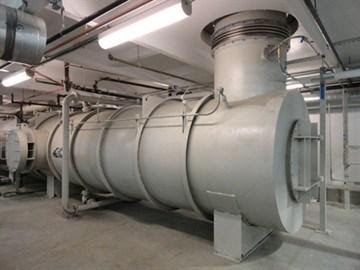
 The DFTO would be exhausting at 1600°F (870°C) so Anguil incorporated three shell and tube heat recovery bundles in series, following the oxidizer. The first two stainless steel heat exchangers would be providing preheated makeup air back to Oven #2 and Oven #3. The process exhaust downstream of that system still contained usable heat, so a third shell and tube heat exchanger was incorporated to preheat the combustion air used in the DFTO. Preheating the DFTO combustion air made the destruction device itself more energy efficient and reduced the amount of supplemental natural gas required.
A summary of this energy recovery project is listed below:
- The shell and tube heat exchangers recover approximately 1.0 MMBTU/h (293 kW/h) to be returned as preheated air back to Oven #2 and Oven #3
- The estimated payback on the heat exchangers is less than 3 months
- The shell and tube heat exchanger to preheat combustion air to the DFTO will recover approximately 0.18 MMBTU/h (53 kW/h)
- The estimated payback on the combustion air heat exchanger is less than 7 months (based on a natural gas cost of $10.00/MMBTU and assuming 24 hour/day operation)
To treat the higher flow, lower concentration exhaust from the ovens, Anguil selected an RTO. This type of oxidizer is capable of 98-99%+ destruction efficiency with very low operating costs compared to other emission abatement technologies. With achievable thermal efficiency over 96% the RTO is capable of operating with little to no supplemental fuel use.
During operation the emission laden process gas enters the RTO through an inlet manifold to flow control poppet valves that direct this gas into energy recovery chambers to be preheated. The process gas and contaminants are progressively heated in the ceramic media beds as they move toward the combustion chamber.
Once oxidized in the combustion chamber, the hot purified air releases thermal energy as it passes through the media bed in the outlet flow direction. The outlet bed is heated and the gas is cooled so that the stack temperature is only slightly higher than the process inlet temperature. Poppet valves alternate the airflow direction into the media beds to maximize energy recovery within the oxidizer.
In keeping with the overall goal of the oxidation system to provide all of the required preheated makeup air back to the ovens, Anguil installed a secondary heat exchanger following the RTO. The plate-type heat exchanger recovers 70+% of the RTO exhaust energy. That preheated air is used in lieu of ambient air for the oven.
- The plate heat exchanger will recover approximately 0.42 MMBTU/h (123 kw/h)
- The estimated payback on the heat recovery system is less than 3 months
The project resulted in an overall reduction of emissions and operating expenses for the carbon fiber company. Even on this small pilot line operation, Anguil was able to show a substantial reduction in the overall energy requirement. Due to the success of this project, Anguil will be installing air pollution control equipment on the customer’s full scale production line. The new system will also be energy efficient, keeping with Anguil’s goal of providing air pollution control equipment today to keep our customers profitable tomorrow.
RTO Handles High VOC Loading at Silgan Containers
Comments Off on RTO Handles High VOC Loading at Silgan ContainersRegeneration Game – Originally printed in The Canmaker Magazine – Sayers Publishing Group
The Challenge
As the first generation of oxidizer systems in the industry nears the end of their service life, many canmaking plants face repair or replacement of their existing air pollution control systems. Like many others in the industry, a Silgan canmaking plant in the Midwest had been using a thermal recuperative oxidizer with direct heat recovery for control of emissions from its sheet coating lines. After more than a decade of service, the oxidizer was reaching a point that repairs would be needed in order to continue to meet strict compliance limits so Silgan began looking for an effective, efficient solution.
The Solution
Historically, thermal recuperative oxidizers with direct heat recovery have been a popular choice in canmaking facilities – especially those with oven zones operating above 350 deg F (177 deg C).
In the past, thermal recuperative oxidizers had a capital cost advantage over regenerative thermal oxidizers (RTOs) and boasted much more flexible Volatile Organic Compounds (VOC) loading limitations. Their one drawback has always been in supplemental fuel usage. Thermal recuperative oxidizers top out at 70 percent internal heat recovery, whereas RTOs are able to achieve more than 95 percent.
For canmakers, this drawback was minimized with the use of additional heat recovery. Hot, purified air from the oxidizer is routed directly back to the oven zones and not lost to the atmosphere. This has reduced the operating cost ‘penalty’ of the thermal recuperative oxidizer and – in the past – has swung the balance toward specifying that system for VOC loads above ten percent Lower Explosive Limit (LEL) almost exclusively.
So exclusively that, when hearing that Anguil Environmental Systems had recommended an RTO for its Midwest coating facility, Silgan responded almost incredulously: “They recommended what? This is clearly not an RTO application.”
Given the technologies offered when Silgan made its initial selection of a thermal recuperative oxidizer, this was an understandable response. It also served as an ideal framework to study what has changed in oxidizer design over the past decade to reverse such a drastic initial response:
- Thermal recuperative oxidizers no longer have capital cost advantage
- With hot gas bypass and feed forward technology, RTOs are now specified in situations up to 25 percent LEL
- With fuel costs being unstable and still on the rise, every heat recovery percentage points counts
- New requirements for VOC capture plus destruction have marginalized direct heat recovery and increased the operating cost gap between thermal recups and RTOs.
Silgan’s existing thermal recuperative oxidizer was designed based on volume of airflow, organic vapor concentrations and desired destruction efficiency. During operation, VOC-laden air is drawn into the system fan and is discharged into a heat exchanger. The air is preheated through the tube side of the heat exchanger and then passes the burner, where the contaminated air is raised to the thermal oxidation temperature (1,200-1,800 deg F / 650-1,000 deg C). When the VOC-laden air is raised to the thermal oxidation temperature for the specified residence time (0.5-2.0 seconds), an exothermic reaction takes place. The VOCs in the air stream are converted to carbon dioxide and water vapor. The hot, purified air then passes on the shell side of the heat exchanger where the energy released by the reaction is used to preheat the incoming solvent laden air reducing the system’s fuel consumption. Finally, the contaminant-free air is exhausted into the atmosphere.
A weakness in all thermal recuperative oxidizer designs is that the steel in the heat exchanger is exposed to high burner chamber temperatures (typically up to 1600 deg F / 871 deg C). The system at Silgan had a history of requiring ongoing maintenance in this area, which had been driving up cost and impacting throughput. The engineering team at Silgan needed to fix the aging system, replace it with an equivalent, or look for alternative equipment.
After evaluating several options, the RTO selection was based on the capital cost advantage and operating cost savings. It would be a custom-built abatement system designed specifically for this application with high loadings and concentrations. Anguil would design, manufacture and install a 40,000 SCFM (64,200 Nm3/hr) RTO with heat recovery, hot gas bypass and oven purge system.
The Result
Silgan’s new RTO operates as follows:
- The solvent laden process gas enters the oxidizer through an inlet manifold. Flow control, poppet valves direct this gas into one of two energy recovery chambers where the process gas is preheated. The process gas and contaminants are progressively heated in the inlet ceramic bed as they move toward the combustion chamber.
- The VOCs are oxidized in the combustion chamber, releasing thermal energy in the ceramic bed that is in the outlet flow direction from the combustion chamber. The outlet ceramic bed is heated and the gas is cooled so that the outlet gas temperature is only slightly higher than the process inlet temperature. Flow control, poppet valves routinely alternate the airflow direction into the ceramic beds to maximize energy recovery within the oxidizer. The VOC oxidation and high energy recovery within these oxidizers reduces the auxiliary fuel requirement and saves operating cost. For example, at 95 percent thermal energy recovery, the outlet temperature may be only 70 deg F (40 deg F) higher than the inlet process gas temperature with an RTO. The oxidizer can reach self-sustaining operation with no auxiliary fuel usage at typical operating concentrations. The process emissions at the Silgan facility as well as the temperature of the oven zones presented some challenges, as well as opportunities.
- With process LEL levels as high as 14 percent there was a concern over high temperature in the RTO. A hot side bypass valve was provided to allow excess RTO reaction chamber heat to be vented directly into the exhaust or the back to the oven inlet manifold during periods when the inlet VOC loading provides more heat than is necessary to maintain the set point temperature. This primary heat recovery saves thousands of dollars in operating costs because the ovens require much less fuel to reach the desired temperature. With the Anguil design there is no loss of residence time at temperature, ensuring destruction and eliminating the concern of overheating the unit. VOC destruction efficiency is guaranteed whether the bypass is open or not.
Silgan is also investigating another energy reduction strategy by using a secondary heat exchanger to recover additional heat from the RTO exhaust stack. Initial estimates show that an extra 6.5 million btu/hr can be recovered by utilizing a heat exchanger in the oxidizer stack. Fresh air (at an average outdoor temperature of 46 deg F / 8 deg C) passes through a single pass 50 percent effective heat exchanger and is heated up to approximately 350 deg F (177 deg C). This recovered heat can be used for processes or comfort heat during the winter months, which could translate into significant savings. - The RTO is also equipped with a high temperature bake-out system, very similar to the self-cleaning option in an oven. This feature removes organic build-up on the cold face of the heat exchange media. In the bake-out mode, the RTO is taken off-line from the process. At a reduced airflow, the outlet temperature is allowed to reach an elevated temperature before the flow direction is switched. This hot air vaporizes organic particulate, essentially clearing the media bed of any obstruction. The flow direction is then switched and the opposite cold face is cleaned. Standard bake-out occurs at 650 deg F (343 deg C), stainless steel media supports and poppet valves were used on the Silgan system that allowed bake-out temperatures to reach 800 deg F (427 deg C), ensuring a more complete cleaning. Scheduled RTO bake-outs reduce the pressure drop across the heat recovery beds. Therefore, Anguil included the transmitters necessary to monitor media bed pressure drop and provide both continuous recording of this data as well as an indication to the operators when a bake-out is recommended.
Dan Gallo, Silgan’s area manager of manufacturing, was pleased with the outcome. “We selected Anguil because of its technical excellence and commitment to service,” he said. “Not only has the company been able to troubleshoot its own equipment, but Anguil has also provided operating solutions for oxidizers made by other manufacturers. We are pleased with their dedication to excellence and are happy to have Anguil as a business partner.”
* Mike Scholz is a Technical Services Engineer at Anguil Environmental Systems.
Canmaker Achieves Cost-Effective Compliance
Comments Off on Canmaker Achieves Cost-Effective Compliance The Challenge
 The Challenge
JL Clark, headquartered in Rockford, Illinois, is no ordinary packager. The company, which celebrated its 115 year anniversary in 2019, is recognized around the world for its award winning metal lithography and exact graphic reproduction.
Also recognized as a long-time positive corporate influence in the community, the management of the company was naturally concerned about the need to comply with US EPA regulations specific to air quality, specifically Volatile Organic Compound (VOC) and Hazardous Air Pollutant (HAP, or air toxics) control. With legislation looming on the horizon, in early 2003 the company began a thorough review of the pending EPA requirements and a corresponding search for a company that could provide a system that would exceed the minimum requirements and do so as cost-effectively as possible.
This was not the first time that JL Clark had taken steps to control their emissions. Years earlier, the company had installed several recuperative thermal oxidizer (RTO) systems that had satisfied earlier requirements but had, over the years, become outdated and was a significant drain on the plant’s operations budget. Costs to operate the systems had become a major component of Clark’s annual fuel usage.
The Solution
After an exhaustive search and thorough review of various proposals, JL Clark selected Anguil to partner with them to meet their emission requirements and at the same time reduce their operational costs. After a kick-off meeting, all parameters were established and agreed upon and work was begun.
The Anguil solution included a 50,000 SCFM (80,250 Nm3/hr) Regenerative Thermal Oxidizer (RTO) to control the emissions and a Permanent Total Enclosure (PTE) to capture the emissions from the plant’s six presses. The selection of the RTO technology was important because it guaranteed the requirement of at least 98% destruction of the VOCs but also because it was seen as an effective way to reduce overall plant operation costs because of its inherent lower operating costs compared with the current VOC control devices.
HOW THE REGENERATIVE THERMAL OXIDIZER WORKS
The Anguil Regenerative Thermal Oxidizer (RTO) destroys air toxics and VOCs that are discharged in industrial process exhausts. The Anguil system achieves VOC destruction through the process of high temperature thermal oxidation, converting the VOCs to carbon dioxide and water vapor, recycling released energy to reduce operating costs.
Process gas with VOC contaminants enters the two chamber RTO through an inlet manifold. A flow control valve directs this gas into an energy recovery chamber which preheats the process stream. The process gas and contaminants are progressively heated in the stoneware bed as they move toward the combustion chamber.
The VOCs are then oxidized, releasing energy in the second stoneware bed, thereby reducing any auxiliary fuel requirement. The stoneware bed is heated and the gas is cooled so that the outlet gas temperature is only slightly higher than the inlet temperature. The flow control valve switches and alternates the stoneware beds so each is in inlet and outlet mode. If the process gas contains enough VOCs, the energy released from their combustion allows self-sustained operation. For example, at 95% thermal energy recovery, the outlet temperature may be only 77° F (25° C) higher than the inlet process gas temperature. PLC-based electronics automatically control all aspects of the RTO operation from start-up to shutdown so that minimal operator interface is required.
THE IMPORTANCE OF THE PERMANENT TOTAL ENCLOSURE
PTEs contribute significantly to the reduction in VOCs released to atmosphere. VOC reduction by a pollution control device only can affect the VOCs delivered to this device. There can still be significant fugitive emissions from the processes which need to be accounted for. For example, older processes with capture efficiencies of 70-85% can result in sufficient emissions that can cause the facility to reach a facility emission cap even with pollution control equipment installed. The installation of a PTE can allow the facility to capture 100% of those process emissions if certain criteria are reached with the PTE design and installation. This high capture rate, along with high VOC destruction rates of new or modified equipment, will significantly decrease the overall emissions from a facility. This reduction can allow for additional expansion of production equipment emitting VOCs without reaching the facility emission limit. The PTE installation can effectively allow for additional production capacity.
In 1990, the EPA issued a capture efficiency guideline which would allow the user the legal presumption of 100% capture efficiency of VOCs without the requirement for formal capture testing. Specifically, the following description applies:
If a source is located inside a “total enclosure” and all emissions are directed to a control device, the requirement to measure the efficiency of capture is waived and presumed 100%. By definition then, a “total enclosure” precludes fugitive emissions. Such an enclosure can be described as a structure that completely surrounds or enshrouds an affected facility such that all VOC emissions are contained and directed through an exhaust stack or into an oven.
THE REGULATION
On November 13, 2003 the US EPA issued a final rule promulgating national emission standards for hazardous air pollutants (NESHAP) for metal can surface coating operations located at major sources of hazardous air pollutants (HAP). These standards (5700 liters/1,500 gallons of coatings per year) dictate that plants affected by this derivative of the Clean Air Act must meet HAP emissions standards reflecting the application of the Maximum Achievable Control Technology (MACT). The standards outline various control requirements based on usage of affected compounds but also provide for emission reduction via a capture system in conjunction with the pollution control device.
The Result
JL Clark’s forward thinking and alliance with Anguil produced a capture system and pollution control device that not only meets the since-enacted EPA requirements but exceeds them. The PTE has proven effective at capturing the emissions from the wet-end coating operations of the process lines-that exhaust is combined with the exhaust from the ovens at the inlet of the RTO. This results in 100% capture efficiency of the VOC/HAP emissions assuring capture efficiency requirements and eventual destruction. The high-efficiency RTO itself has proven to be similarly effective, achieving destruction efficiency in excess of 99% while exceeding all fuel usage reduction objectives! The combined capture and destruction efficiency has therefore exceeded 99% for the facility, minimizing the overall VOC/HAP emissions from the facility and allowing the facility to meet their emissions cap.
The result is a partnership that further enhances JL Clark’s reputation as an industry and community leader and provides Anguil with yet another satisfied customer, one of almost 1,500 around the world.
Coater Replaces Old Oxidizers with Energy Efficient Systems
Comments Off on Coater Replaces Old Oxidizers with Energy Efficient SystemsTHE CHALLENGE
Emission control, and the operating costs associated with meeting environmental regulations, were nothing new for the Coated Products Division of Brady Corp. For nearly 60 years Brady Corp has been manufacturing coated films, demonstrating over that time a commitment to pollution prevention and emission reduction programs. These considerations were magnified when the Milwaukee coating facility chose to implement a new energy-efficient emission control system.
The division maintains 200 different coating formulas on three main continuously operating process lines. Two of the company’s three coaters are operated as so-called “white rooms” to allow the manufacturing of exceptionally clean products. Applying adhesives, topcoats, cast films and other coatings onto a range of substrates requires solvent-based coatings with mixtures of chemicals. Some of the many solvents used in the process are: toluene, MEK, MIBK, heptane, hexane, ethyl acetate, IPA, nitroethane, nMP, cyclohexanone, and 1,3-dioxolane. The dynamic process stream poses many challenges to the company, particularly since it eliminates the option of solvent recovery.
THE SOLUTION
If careful consideration is not given to proper equipment selection, the initial cost of emission control equipment can be negligible compared to the operating costs. With natural gas prices continuing to rise, Brady focused on getting the most efficiency from its incineration equipment.
Since the early 1990s, the facility has spent millions of dollars on air pollution control equipment to meet a variety of Environmental Protection Agency (EPA) regulations imposed on coating companies. The purchases have included thermal recuperative and regenerative thermal oxidizers (RTOs), as well as concentrator systems. For the Milwaukee location alone, Brady has purchased a total of 12 units with a 13th on order. The oxidizers have been used to treat everything from coating emissions to low-point floor sweeps located throughout the facility. As natural gas prices have risen, and with associated costs for emission control equipment steadily increasing, Brady sought ways to reduce their yearly operating and maintenance costs, which were overwhelming.
When one of the old electric RTOs failed, the downtime averaged over a week to replace the cold face support grid and electric heating elements before bringing the unit back up to temperature. The failures happened so frequently, the maintenance department constructed a special tent so the repairs could be done in the rain or snow. The thermal recuperative oxidizers on site had many problems with internal heat exchanger failure; a roller system was installed just to move the large duct transition, allowing access to weld the tube sheet without bringing in a crane.
To reduce maintenance costs, a decision was made to begin replacing the oldest and least efficient oxidizers. The type of systems would be determined by the maintenance team. The first phase of what plant personnel started referring to as its “efficient emission control plan” would replace one of the thermal recuperative oxidizers with a 35,000 SCFM (56,175 Nm3/hr) RTO from Anguil Environmental Systems.
The new system tested out at a destruction efficiency rate of 99.2 percent and was equipped with a hot-gas bypass that allowed it to process volatile organic compounds (VOCs) at rates up to 850 lbs/hour. This high-capacity VOC processing allowed some of the other less-efficient oxidizers to shift their load over to the new RTO through a unique common manifold collection system. With the increased concentration of hydrocarbons in the process air stream, the heat energy content of the VOCs was self-sustained, and the oxidation process required no additional fuel for destruction.
RTO technology utilizes ceramic media in two or more beds as a high-efficiency heat exchanger. Process gas with VOC contaminants enters the RTO through an inlet manifold. A flow diverter valve diverts the gas into an energy recovery chamber, which preheats the process stream. The process gas and contaminants are progressively heated by the ceramic bed as they move toward the combustion chamber.
The VOCs are then oxidized, releasing energy that is transferred to the second ceramic bed, thereby reducing any auxiliary fuel requirement. Heat is transferred from the gas to the ceramic bed so that the outlet gas temperature is only slightly higher than the inlet temperature. A flow diverter valve switches, alternating the ceramic beds so each is in inlet and outlet mode over time. If the process gas contains sufficient VOCs, the energy released from their combustion promotes self-sustained operations. For example, at 95% thermal energy recovery (TER), the outlet temperature may be only 77°F higher than the inlet process gas temperature.
The Brady maintenance team investigated several types of RTO systems, including a new rotary valve system. The rotary valves seemed to be a viable option at first inquiry, but they were a close-tolerance proprietary item that could only come from a specific vendor. A major maintenance concern was the location of the rotary valve. It was discovered to be situated underneath the RTO, presenting logistical issues. Ultimately, Brady chose Anguil’s poppet valve design, believing the maintenance access was more satisfactory. Brady was surprised, and pleased that Anguil was willing to share its complete computer operating program, something other vendors were not willing to do.
Other items on the system included:
- A stairway for access to platforms rather than the usual vertical ladders – a feature especially appreciated in Wisconsin winters
- Replaceable valve seats on the poppet valves and large access doors
- Heavier gauge access doors with fewer bolts to be removed
- Block-off plates after the system fan as required for confined space entry
The second stage of the plan would prove to be a little more challenging, but even more helpful in reducing the company’s operating costs. The EPA’s requirement of a permanent total enclosure (PTE) requires coaters to create negative pressure in all areas of the facility that process any volume of solvents. Due to the layout of the coaters, this became a large volume of exhaust air with very low VOC levels.
Two of the old electric RTOs were treating this high-volume, low-concentration stream from pump rooms, wash-up areas, compounding areas, and floor sweeps located throughout the facility. Large volumes of natural gas were consumed to burn a very small amount of pollutants. In addition, the unit could not be turned off during plant shutdowns because of time-consuming reheat procedure, which could take up to four days.
After evaluating the solvent vapors and various concentrations, an Anguil Model 350 (35,000 SCFM or 56,175 Nm3/hr) rotor concentrator and Model 50 (5,000 SCFM or 8,025 Nm3/hr) RTO were selected to handle this portion of the process. By absorbing and concentrating the VOCs they were able to achieve a 10-to-one concentration ratio, requiring an oxidizer only a tenth the size to handle the concentrated process stream. The energy contained in the concentrated stream entering the RTO proved sufficient to allow self-sustaining operation, requiring little to no auxiliary fuel.
THE RESULT
The third, but not final, stage of Brady’s plan is still in motion. They have placed an order for another 35,000 SCFM (56,175 Nm3/hr) RTO to replace the last thermal recuperative system on site. When this system has been installed, heat from the RTO will be used to preheat the facility’s ovens, further reducing energy consumption. The system will have enough capacity to eliminate the final thermal recuperative unit and another aging electric RTO.
In addition to replacing old oxidation technologies at the facility, careful consideration has been given to all the oxidizers as a single system. The company has implemented a dual collection and distribution manifold that allows operators to divert process streams from one oxidizer to another for maintenance or equipment shutdowns.
The impact of these efforts has exceeded expectations for reliability and efficiency. Gas usage on the company’s three coating lines have continued to drop at a steady rate. At a time when gas prices continue to trend high, coupled with increases in production, the reduction in energy consumption drops straight to the bottom line.
Brady Corp is continuing to explore energy reduction strategies and is currently investigating the option of placing secondary heat exchangers on all of its oxidizers. The process would return waste heat to preheat the air streams on all of its other coating lines.